March 5, 1932—February 5, 2013
A Retired Dentist Turns His Skills Toward Aluminum Aircraft Models
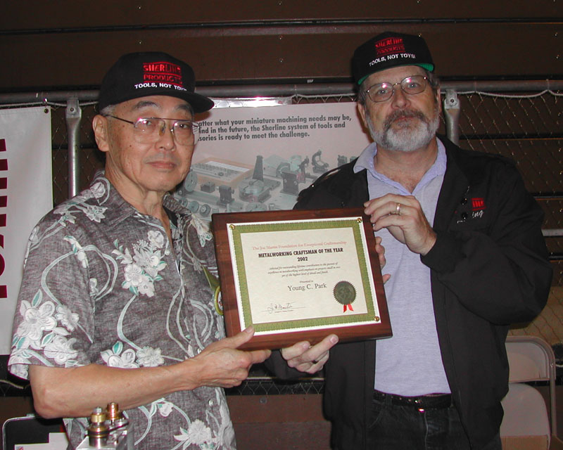
Joe Martin Foundation Craftsman of the Year Award Winner for 2002
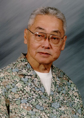
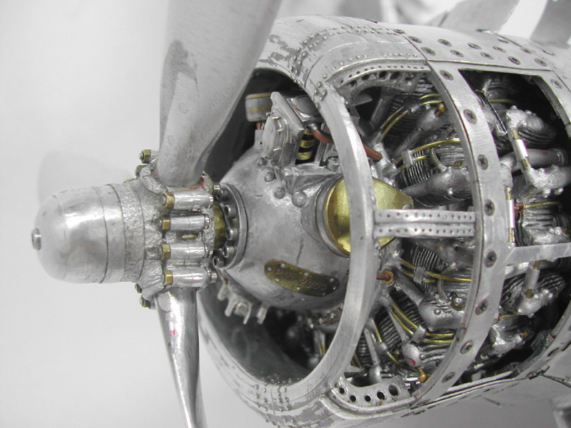
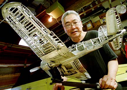
Young C. Park of Honolulu, HI, began modeling aircraft in his childhood. After retiring from his career as a dentist, Mr. Park went on to fulfill a lifelong dream of building a model airplane entirely from aluminum.
About Young C. Park
Oddly enough, Young Park seemed amazed that his work was admired by other craftsman. Park admitted that his work was unusual and unique, but when compared to that of a precision machinist, he saw many faults in his own projects. Because of this, he was hesitant to share his accomplishments beyond his local community.
Every part of Young’s planes were completed to his personal satisfaction. He built them solely by his own standards and expectations. Mr. Park didn’t build these masterful miniatures for entry in shows or contests. He noted that it was less important that the parts be technically perfect, so long as they “look and fit right.” With cutaway sections on some of these incredible miniatures, viewers can see that making these complicated parts come together is true artistry.
Despite Mr. Park’s humility, his aircraft models speak for themselves. When considering the number of coordinated actions that must take place for a wing to fold up, or a landing gear to rotate into position, or for any control surface to move with its respective cockpit control—there is no denying Young’s mastery. A microscopic inspection of each part would reveal that most are not technically perfect. However, the completed aircraft—with all of their complicated, interrelated mechanisms and functional controls—are themselves more ambitious feats than most model craftsman would even contemplate. Taken as complete metal sculptures, without microscopic criticism, the models look absolutely perfect.
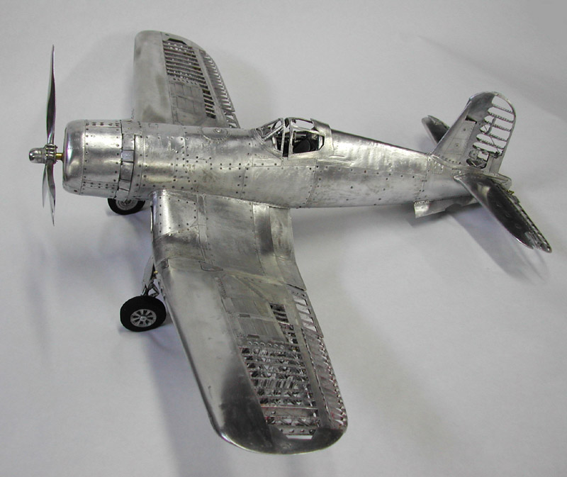
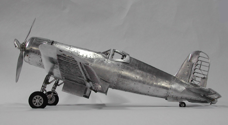
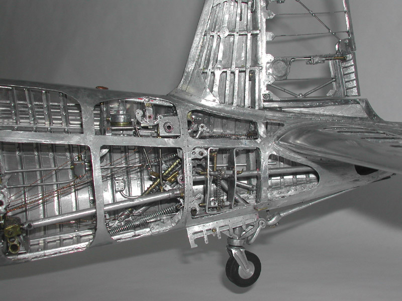
An overall view of Young’s finished 1/16 scale Corsair. Most of one side has the outer skin, while the other side was left as a cutaway to reveal the internal components. The wings actually fold, the wheels and hook retract, and the controls work. This miniature aircraft took about 6,000 hours to build over a period of 5 years. (Photo courtesy of Augie Salbosa.)
Interestingly, some of Young’s handiwork is visibly noticeable on certain parts . However, these “maker’s marks” give the finished models a character that would be lost if a real Corsair had been shrunken down to scale with absolute exactness. It’s much like the difference between a perfect photograph and a great painting. The photograph is an exact image, but the painting has a quality which brings the viewer back again and again—appreciating new elements each time. Young C. Park was truly an artist in metal.
Before bringing his models to the North American Model Engineering Society Expo in Detroit in 2002, Young had only ever shown them to a few friends, and a local model club. As such, he was a little apprehensive to display them for the machinists, metalworking craftsmen, and hobbyists attending a model engineering show.
In reality, the craftsmen at this show were among the best qualified to appreciate the skill it takes to scratch-build models to this level of detail—and without using any dimensional plans! Unsurprisingly, Young’s models were received with overwhelming approval. We thank Mr. Park for making the long trip—and risking his models in the shipping process—to share them with peers who could really appreciate his remarkable accomplishment.
Before his passing, Young recalled that weekend as one of the most enjoyable of his life. Undoubtedly, many attendees of the show who were able to see Mr. Park’s models would agree that it was a special experience because of his attendance.
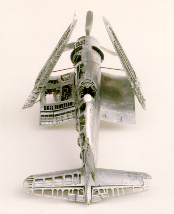
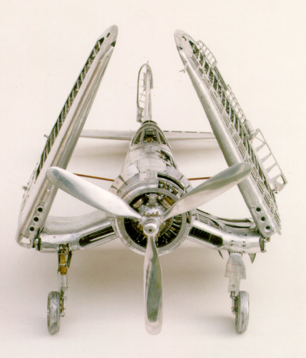
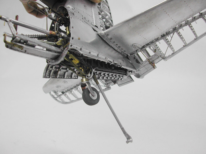
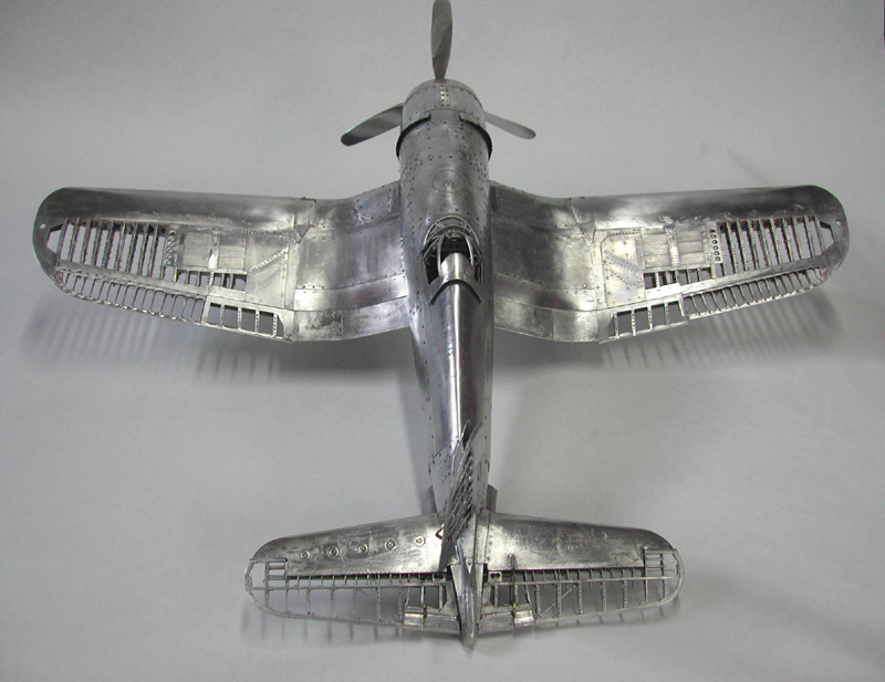
A rear view of the Corsair with the wings folded up into storage position. This unique design allows these planes to take up less space on an aircraft carrier flight deck. (Photo courtesy of Augie Salbosa.)
Projects Donated to the Miniature Engineering Craftsmanship Museum
Following the NAMES Expo in 2002, Young Park graciously donated the first of his 1/16 scale Corsair models to the Miniature Engineering Craftsmanship Museum in Carlsbad, CA. Then, in 2005 he donated his second Corsair model. The first is fully paneled on the right side, but modeled as a cutaway on the left side. The cutaway reveals all of the internal workings of the wings and fuselage.
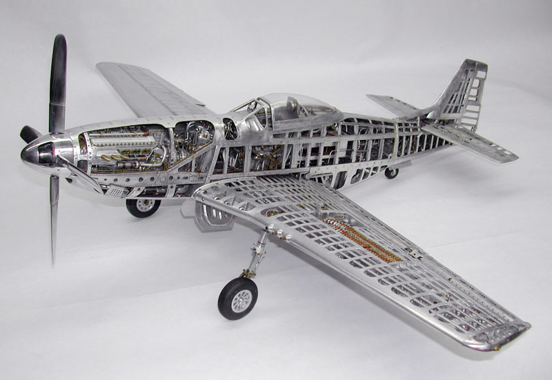
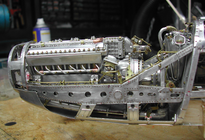
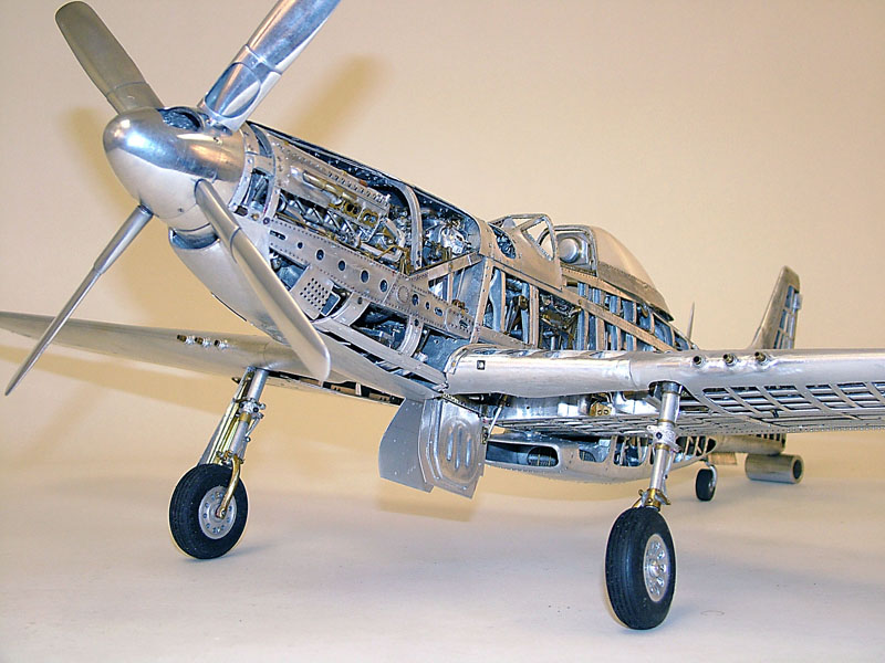
Young’s second Corsair is fully paneled, but made in four sections like the original plane. As such, the model can be disassembled, and the motor removed to show the internal components. In 2006, it came as an even greater surprise when we received Mr. Park’s recently completed P-51 model. The Joe Martin Foundation is especially honored, as this was Young’s final project.
Three years in the making, the P-51 model represents the culmination of Mr. Park’s metalworking and modeling skills. The details, working parts, and panel fits must be seen to be truly appreciated. These models are now on display at the Miniature Engineering Craftsmanship Museum, but Young also contributed many photos for eager viewers to appreciate here.
Additionally, Young also compiled a collection of photos and historical data on the Corsair into a binder, detailing his construction process throughout. This was also donated to the museum for viewing alongside the models themselves.
Young’s second aluminum Corsair, which was made at the same scale as the first, but built differently. Mr.Park felt that his skills had increased after the first model, and he wanted to make the second even better. On this model, the fuselage comes apart in four sections, much like the real aircraft.
Autobiography
The following biographical information was provided by Young C. Park. In addition to that, Young also provided a write-up on the processes he used to create his super-detailed aluminum Corsair models, which can be found below.
I was born in Kona on the island of Hawaii on March 15, 1932 to immigrant parents who came from Korea in 1910. I grew up on the opposite side of the island in Hilo. World War II left a lasting impression on me, especially the fighter airplanes with their speed and loud noise.
After the war, I became interested in a new product; the Olson 23, an ignition, gas powered model airplane engine. I delivered newspapers and saved enough to buy my first engine, a Vivall 35. Now I could build an airplane with speed that made lots of noise.
I was fortunate to have an older friend, Louie Carvalho, who was a modeler and taught me all he knew. He was patient, meticulous and understanding. My first U-control model was a failure. Like all beginners, I rushed the model to see how it would fly.
He taught me to be patient, and to do the best I could at each step. I remember Louie teaching me in detail, saying, “Wait for the solder to turn dull,” or stopping me and saying, “Flat washers and nuts have a face.”
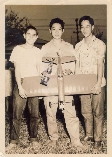
Young C. Park (center) in 1947 at age 15, flanked by friend and mentor Louie Carvalho (left), and another friend to the right. Young had just won a U-control stunt contest in Hilo, HI. The homemade plane sported an Atwood 60 engine. Photographed barefoot here, Young noted that he didn’t start wearing shoes until high school!
Louie took me to a graveyard of World War II airplanes being processed for scrap. I remember seeing 50 caliber machine guns rusting on wings, and being amazed to see that many parts of the fighters were made like a U-control model—cloth painted with dope. I took pieces of aluminum, which was a novelty at the time, and made jewelry as well as bellcranks, control horns and switchplates for my U-control planes.
One day, I said to Louie, “Wouldn’t it be neat to build an all aluminum scale airplane?” I was excited about the idea, but soon became discouraged when I took a mental inventory of my tools. I had an X-Acto knife, a file and a hand drill. Louie passed away at the early age of 25, but I always think of him while modeling to get his silent approval, as he was my mentor.
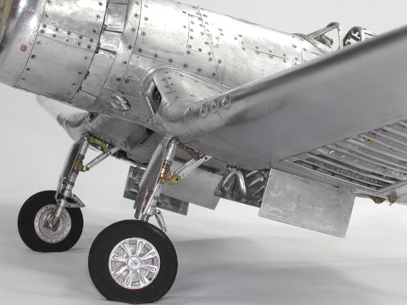
For Young’s second Corsair, most of the wings and fuselage are skinned, giving it a more finished appearance. The tires are actually rubber on this model, rather than aluminum like the first version. For this project, Mr. Park purchased miniature machine tools to make some of the parts more accurately. He mainly used hand tools for the first model.
I was inducted into the army in 1952, and again saw the beautiful Corsairs in Korea. During the next 40 years I continued to build models. I built radio control planes in the era of single channel escapement radios, enjoyed rubber powered planes, and was intrigued with plastic kits when they came out (but could never seem to finish them). Nothing I did in the hobby seemed to bring me total satisfaction.
In 1996, I got the urge to build again, and ordered a Lockheed Vega kit with a 9-foot wingspan, and a 5-cylinder Sidel engine. I built most of the framework and decided to use aluminum for the dash, windshield and window frames. The aluminum parts looked good, so I looked for more parts to convert. I suddenly remembered my long-forgotten dream of an all aluminum airplane.
This was what I had been searching for all these years. I now had the tools and space necessary for my new hobby. I knew I would never work on the Vega again, so I hung the unfinished model in the garage where it remains to this day. Working in aluminum was to bring me the satisfaction I had been seeking.
The Corsair had always been a favorite of mine, so I decided to build its tail fin and rudder to see what it would look like in aluminum. I also decided on moveable trim tabs and rudder, and planned to use it as a decorative piece if I could complete it. At this point, the tail was my only objective. Had I considered building an entire plane, I would have surely become discouraged and never started.
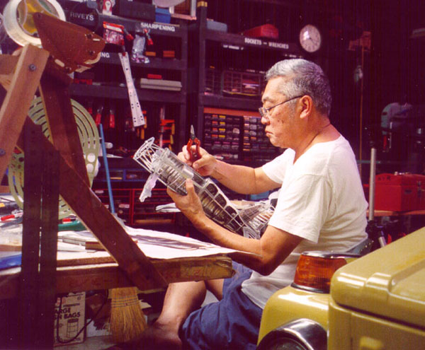
Young Park at work in his shop. He is holding the partially completed fuselage of one of his Corsair models, lending a sense of scale to the miniature plane.
For reference material, I used the plans from the 3/4″ to 1′ scale Guillow kit, and the cutaway and other illustrations by Rikyu Watanabe from The Great Book of World War II Airplanes. I began with these references, and later added more detail with better resources. After a month, the horizontal tail was complete and looked pretty good for a first project.
Next, I added the vertical stabilizer and rudder after doing more research on the structure. I was getting better, and really enjoyed working with the aluminum, so I decided to continue with the fuselage. Three years later, a cutaway model was virtually complete, although I continue to add detail to this day, so it will probably never be “done.”(*Young’s model Corsair was eventually finished, after 5 years of work.)
In making the first Corsair, I ran into some jobs that I could not complete to my satisfaction with hand tools, and knew I would need to learn to use small machine tools to make better parts. I purchased a Sherline milling machine and started on a second model.
This one would be built in sections that could be assembled like the real plane, and would be built to a higher level of quality. I added a Sherline lathe to my shop as well, and am now in the process of finishing the second model.
Up until 2000, the first model had only been seen by a few friends. The president of a model club in Honolulu asked me to display the model in a show at a local mall. I had not really planned to attend, but an article about the model in the Honolulu Star Bulletin announced that the plane would be at the show, so I felt I had to go.
It attracted a fair amount of attention, but there was really nothing to compare it to, as no one else was making all metal models. That article, however, was also published on the internet, and it led to a feature photo article in the November, 2000 issue of FineScale Modeler Magazine.
In the meantime, I had been in contact with the people at Sherline after they found out about the model. I kept them up to date on my progress by sending photos now and then.
I retired from my dental practice in December, 2001 to spend all of my time modeling. In January, 2002 I received a call informing me that I had been selected as the Craftsman of the Year by the Joe Martin Foundation. I was speechless. After seeing the accomplishments of the five former winners and looking at the projects in Joe Martin’s book, Tabletop Machining, I felt like a dwarf among giants. I always thought of my model as being unique and unusual, but not from the machinist’s point of view.
When I see the beautiful precision machining that some of the other modelers do, I feel that I will never be able to achieve that level of perfection, but I do agree that my model has a unique character. I am not so concerned with technical accuracy as I am with the way it looks, and how all the parts fit together.
In fact, I have been asked many times what motivated me to build this unusual model. I had no good answer until I talked it over with Craig Libuse when he notified me of the award. He pointed out that it was not the individual details of the model that were unique, but the interaction of so many parts and how they all fit together.
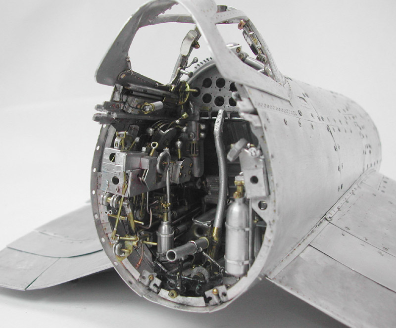
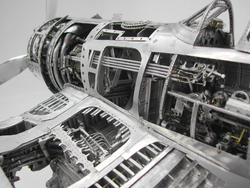
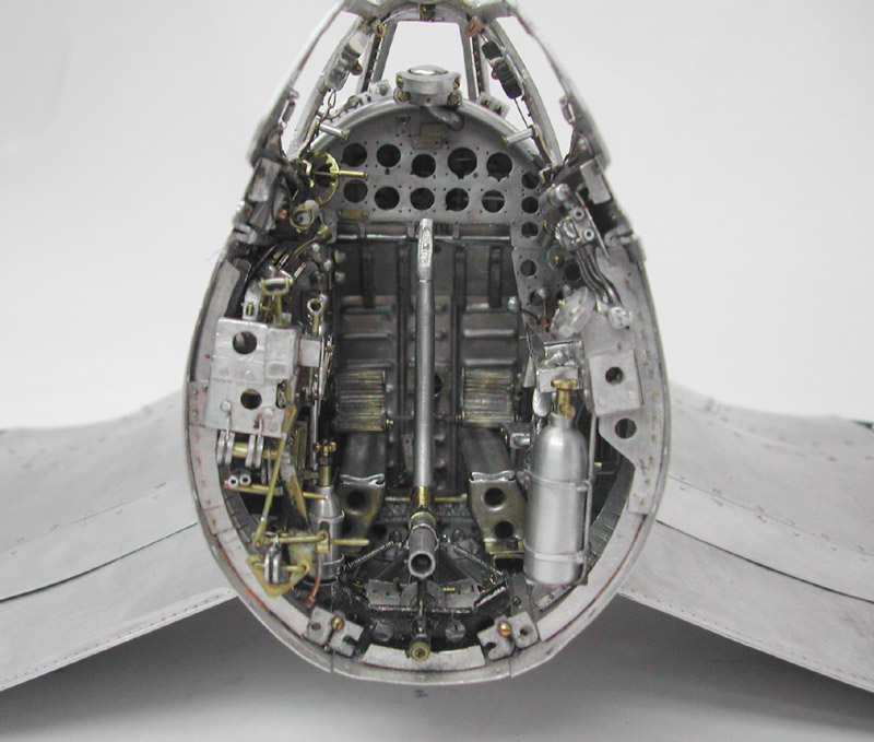
With the model Corsair disassembled, even more of the pilot’s controls are visible inside the cockpit.
I now realize that it is the pleasure that I get from the aluminum material—and the interaction of these parts—that has kept me motivated day and night for the last five years. I hope it will keep me going for another five years at least. As a dentist, I have worked with gold casting, and I find aluminum to have very similar properties. It can be annealed, work hardened, burnished and made malleable.
Living in Hawaii, I appreciate most its non-rusting properties, particularly as I see all of my tools slowly rusting in our salty air. I plan to keep honing my skills, and continuing to work with aluminum. If all goes well, my next project may be a P-51 Mustang. I hope Louie approves.
—Aloha, Young C. Park
Building the 1/16 Scale Fully Aluminum Aircraft Models
By Young C. Park
Mr. Park submitted this follow-up after constucting his second Corsair model.
When I first started work on building just the tail of the Corsair, my first attempts were disheartening. It was difficult trying to hold two pieces at different angles, and expecting them to stay in place. I used “rivets” by drilling holes, inserting pieces of wire and squeezing them together. It became so flimsy that I wanted to stop. I knew if I did, I would never go back to it. So I continued, and slowly the tail became more stable as pieces were added. It took over a month, but the tail looked good for a first project.
Next, I decided to build the stabilizer and elevator using the same method and reference material. It again looked good, so I decided to connect the fin and stabilizer. I needed more reference material to see how this was done.
I collected all the literature, photos and drawings I could find on the Corsair. Most helpful were the copies of the original government manuals dealing with the complete illustrated parts list, and the detailed repair and maintenance sections from AeroTec Data.
I also received photos and scale drawings from Bob Banka’s Scale Aircraft Documentation and Resource Guide catalog. I needed a three-dimensional view, and used the 1/48 and 1/32 scale plastic and resin kits to learn more about the plane—particularly the engine and cockpit.
The Fuselage
I now had visions of making a complete airplane. I decided to build a cutaway model with internal moving parts. I now knew that I must always use a jig or support made from wood—balsa or hardwood—for stability.
I began the fuselage at the tail section using a 3/4” x 3/4” x 30” straight wooden stick as a guide, and temporary central brace. The stick was shaped to accept the tail pieces. Skin and carved aluminum pieces were mounted at the tail end. The fin and stabilizer were aligned and screwed to the skin using round head sheet metal screws for easy removal. Main bulkheads were added and super-glued to the stick.
All construction was started at the rear and moved forward. Pre-shaped aluminum skin was added to the bulkheads. I used the ball of my foot to shape the large area of the skin behind the cockpit. I used a folded towel for padding.
The raised hump directly behind the cockpit (the turtle deck) was annealed and slowly hammered to shape before installation. Now, I try not to anneal skin with single curves because of the “oilcan” effect. I annealed only areas with multiple curves, and areas that can be work hardened. I used the largest piece that could wrap around this area, which gave an even flow and contour to the skin. Panels were cut out after the skin was installed.
The skin was fitted around the bulkheads which were, in turn, pressed against the stick. The initial fit was not good. Tape and rubber bands were used to hold the pieces in place. I wrapped my hands around the skin and slowly squeezed. I cannot describe the sensation of an aluminum fuselage held in my hands. I sometimes think of it as an aluminum sculpture as it takes shape.
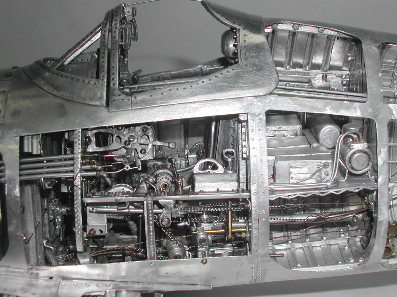
This wing root view of the left side of Young’s Corsair shows access into the wing and cockpit. Throttle controls run through tubes in the fuselage. Hydraulic lines can also be seen inside the wing.
I used the flat side of a 2 x 4, applied pressure, and slowly rolled the wood around the fuselage. The fit slowly gets better. I always kept the ends of the skin pulled tight. I removed the skin to straighten out dents or to move more metal by the previous methods. This was repeated many times until I had a fairly good fit. This procedure took a few days.
The end result is a part of a Corsair model no one had made before. The skin was held to the bulkhead with round head sheet metal screws, size 0 rivets were added, and finally the screws were replaced with more rivets. The screws act as Cleco clips. Flat head sheet metal screws were used on the removable panels. I removed the stick after all of the skin was attached. I now had a half-exposed hollow tube with tail, and good internal access.
I used common aluminum roof flashing for most of the covering and internal parts. The flashing is found in all hardware stores. There are two types: the old stock which I use, and a new stock with lower aluminum content. It is shiny and cannot be annealed because it turns brown before annealing temperature is reached.
Both come in different width and roll lengths. I must have used over 50 feet on my first model. There was a lot of waste due to trial and error, and finding the correct method of annealing.
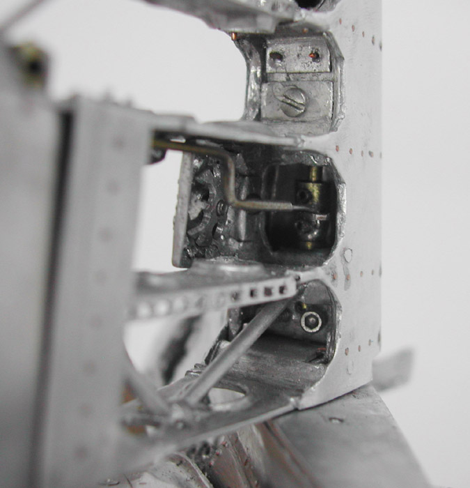
A close-up of the landing gear on Young’s second Corsair model. Many parts are needed to allow the gear to fold and rotate into position while the doors also close. Slight depressions on the inside panels of the gear doors had to be made, just like the original, so that the doors would close without hitting the tires.
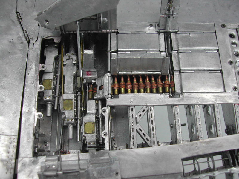
Inside the Corsair wing are three .50 caliber machine guns, and several ammo cans. The ammo cans are loaded outside of the aircraft, and then simply set into place in the wing. The doors for the ammo boxes fold down to make the top surface of the wing. This allowed for rapid reloading by the ground crew.
Annealing Techniques
After much experimentation, I found that using a red Sharpie permanent marker works well as a heat indicator. Draw lines on both sides of the aluminum. Use a brush flame butane torch and slowly heat both sides. The lines will turn brown and disappear completely.
At that point it is properly annealed. I sometimes see a dark orange glow. The aluminum returns to its original color after it is correctly annealed.
If I over anneal a part it is discarded. When correctly done, the soft metal is now easier to form, drill or carve. Carving was done with a Dremel mototool with straight and angled drives. I burned out two before finishing the first model. I have since learned to use my dental handpieces, and a small lathe and mill for the bulk of precision removal.
After three years and 6,000 hours of work on the model, the exterior was completed, and the major internal controls were installed. There were many ongoing improvements and additions. There were many minor controls yet to be installed. I saw no end to the project, so I declared the cutaway model temporarily “completed” so that I could start another project.
Then, I decided to build a better model with what I had learned. I needed more accurate tools, so I bought a Sherline milling machine with a tilting table and rotary table. I milled the wheels and brake drums, and made the gun breech hinges and other parts. They were not very good by machinist’s standards, but ideal for a scratch scale airplane hobbyist. I later added a Sherline lathe to compliment the milling machine.
Ultimately, I decided to do another Corsair. I felt I did not have enough time to do all the research on a new airplane. I was 68 going on 70.
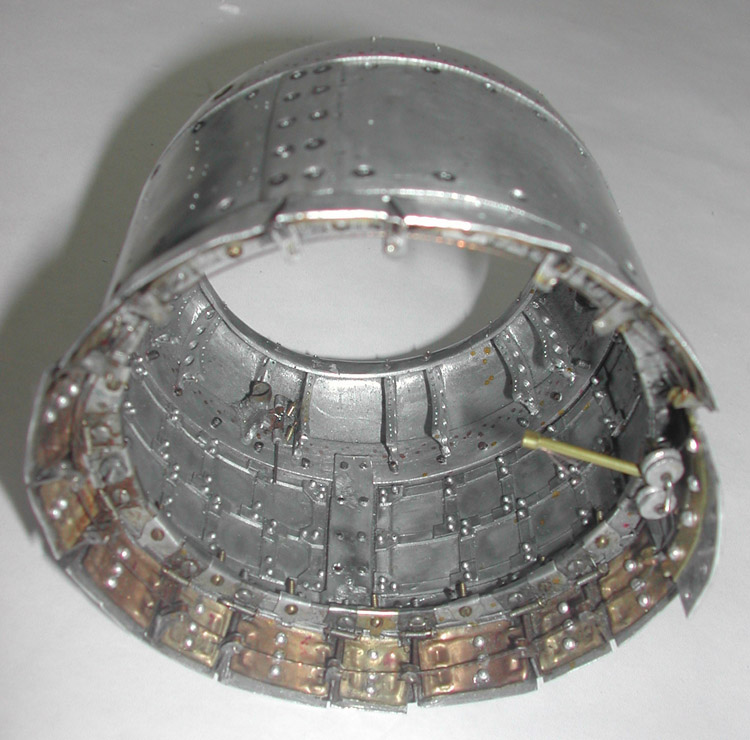
On the first cutaway model, the front curved cowling and wing root intakes were made by stacking solid pieces of metal together, and carving out their anatomy. I now felt I had the skill to hammer out these parts. I decided on a model with a full aluminum covering, and a fuselage that could be put together and removed in four sections like the original.
I planned to deviate from the original by installing many of the removable panels for future access. The Corsair fuselage is a hollow tube mainly supported by its outer shell or skin. Many of the Corsair’s minor joints were originally spot welded.
I inquired about buying an aluminum spot welder, and was politely informed that our household electrical wiring was not compatible with the requirements of spot welding. Instead, I would use 24 gauge wire “rivets.” I could not find that gauge in aluminum, so I settled for sterling silver wire until the craft store supply ran out. Then I used copper and brass. Copper gives a good contrast and is a lot cheaper.
The wires are superglued in place. The large wires are hammered or squeezed in place when possible. Otherwise, they are glued. The major joints on the real airplane—the section-to-section or skin-to-bulkhead connections—were flush riveted. The minor joints—the skin-to-formers and longerons—were spot welded.
Special Tools
When I retired from the practice of dentistry, I did remember to transfer four dental handpieces to my workshop at home. Cutting aluminum for the first time with a high-speed dental carbide drill was a unique experience. It cuts like butter until it digs in and binds or grabs the metal.
The use of cutting oil and very light pressure reduces this problem. Diamond drills are slower, but behavior is better. The first chance I get, I will mount the dental drill on the Sherline lathe and see how it cuts.
I look forward to completing this second model, although I see both as ongoing projects. I will continue to add details and fine tune parts to make them better. The satisfaction I have received from making them has inspired me to begin to think about future projects, such as a P-51 Mustang.
(Update: The P-51 was completed in early 2006, and has been donated to the Miniature Engineering Craftsmanship Museum, along with the first two Corsair models. Photos can be seen below.)
Using Glue on Aluminum Aircraft Models
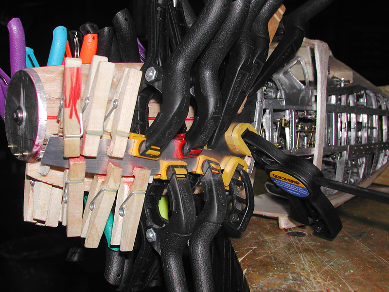
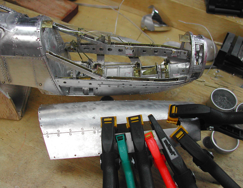
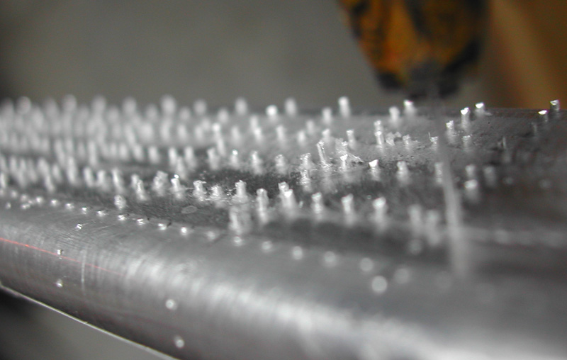
Visitors to the museum have probably asked if I used glue to build the models. Let me clarify how I used glue on some of the skin and other parts. The photos below show lots of clamps holding down glued parts to temporarily hold the part to the frame so I can “rivet” the piece. The builders of the real airplane used what are called Cleco clips to temporarily hold the skin to the frame. When I was in Seattle, I visited Boeing Aircraft and bought different types of surplus Cleco clips to see how they worked.
They insert hundreds of these clips into the rivet holes, and tighten the clips to draw the skin to the frame. A really neat tool! I used the glue to stabilize the piece so I could rivet, or in some cases screw the piece together. I let the glue—either goop or shoe glue thinned with toluene—set overnight. None of the skin depends on the glue to stay in place after riveting. The models were built like a tank, with many screws, true rivets, and false rivets—that is, wire super-glued to the skin and frame.
I feel that none of the major parts will come apart. For the false rivets I used the thinnest, most expensive superglue (cyanoacrylate) I could obtain. It was called “triple distilled,” which is how superglue is or used to be graded. I dipped the wire into the glue and quickly threaded the wire through the rivet holes, being aware that moisture quickly sets the glue.
—Young C. Park
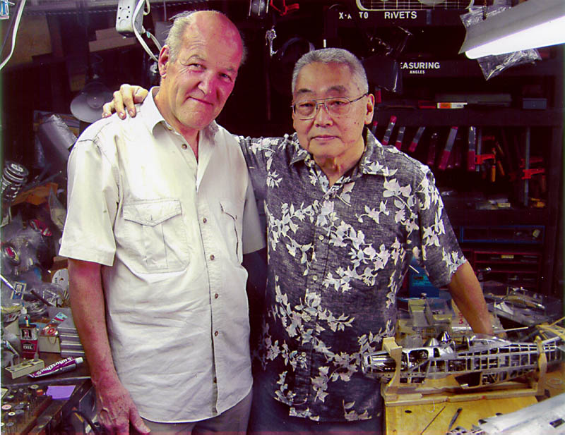
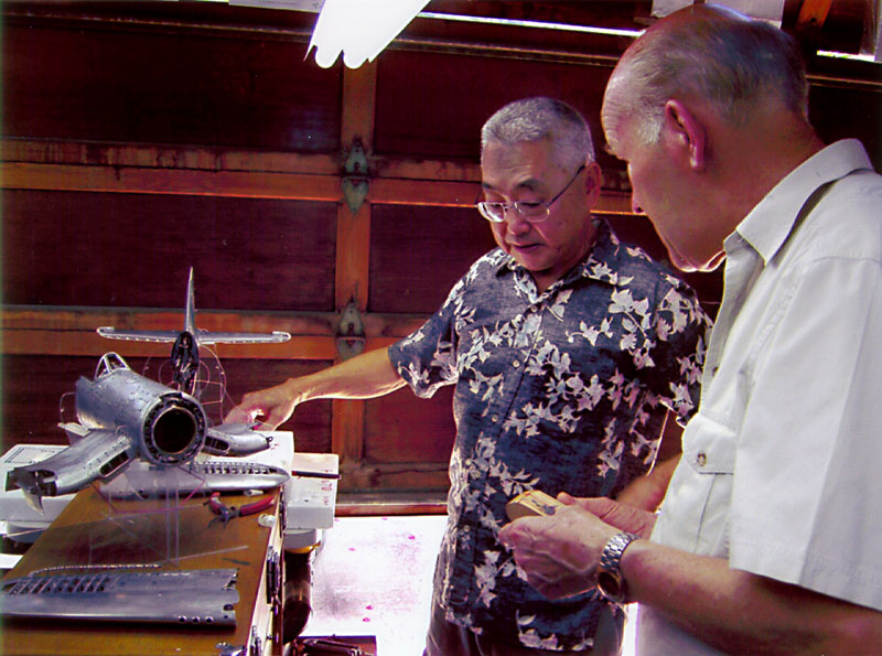
Young Park was visited in his shop by the 2005 Craftsman of the Year winner, Gerald Wingrove. Gerald and his wife, Phyllis were visiting Hawaii to do research on the iron-hulled clipper ship, Falls of Clyde. The original ship was docked in Hawaii, so Gerald stopped by to visit with the 2002 Craftsman of the Year. Gerald inspected some of Young’s work on the Corsair before it was donated to the Craftsmanship Museum for display.
Articles on Young’s Aluminum Aircraft
- Read an article on Young Park’s Corsair from Fine Scale Modeler magazine (Sept., 2005).
-
Read an article on Young Park’s P-51 Mustang from Fine Scale Modeler magazine (Sept., 2008).
-
Read an article on Young’s Corsair from the Russian edition of Popular Mechanics magazine (March, 2010). (English translation provided.)
-
Shortly after his passing, the German magazine Flugzeug Classic 5 published an article on Young Park and his planes (May, 2013).
View more photos of Young C. Park’s marvelous scale model aircraft.
Young C. Park passed away February 5th, 2013 in Honolulu, Hawaii. His three aluminum model aircraft remain on permanent exhibit at the Miniature Engineering Craftsmanship Museum in Carlsbad, CA. We thank Mr. Park for his commitment to excellence in scale model engineering.
This section is sponsored by:
Makers of precision miniature machine tools and accessories. Sherline tools are made in the USA.
Sherline is proud to confirm that Young C. Park used Sherline tools in the production of his aircraft models.

