The Seal Engine Project—Full Build
Below we have documented the Joe Martin Foundation Seal engine build from start to finish. Photos and descriptions of the components illustrate the unique collective craftsmanship—with a beautiful final result.
Seal Engine Project Starts (7/25/06)

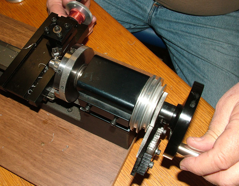
Seal Engine Casting
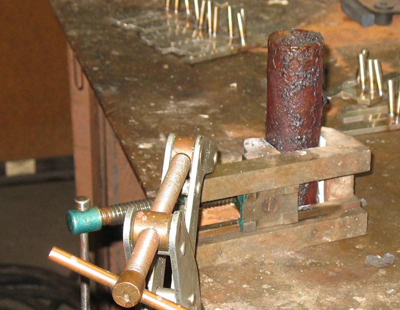
The first cast part for the Seal engine is machined on the lathe. The back surface was being flattened here. The engine required many parts that were custom made from bar stock, too. (7/25/06)
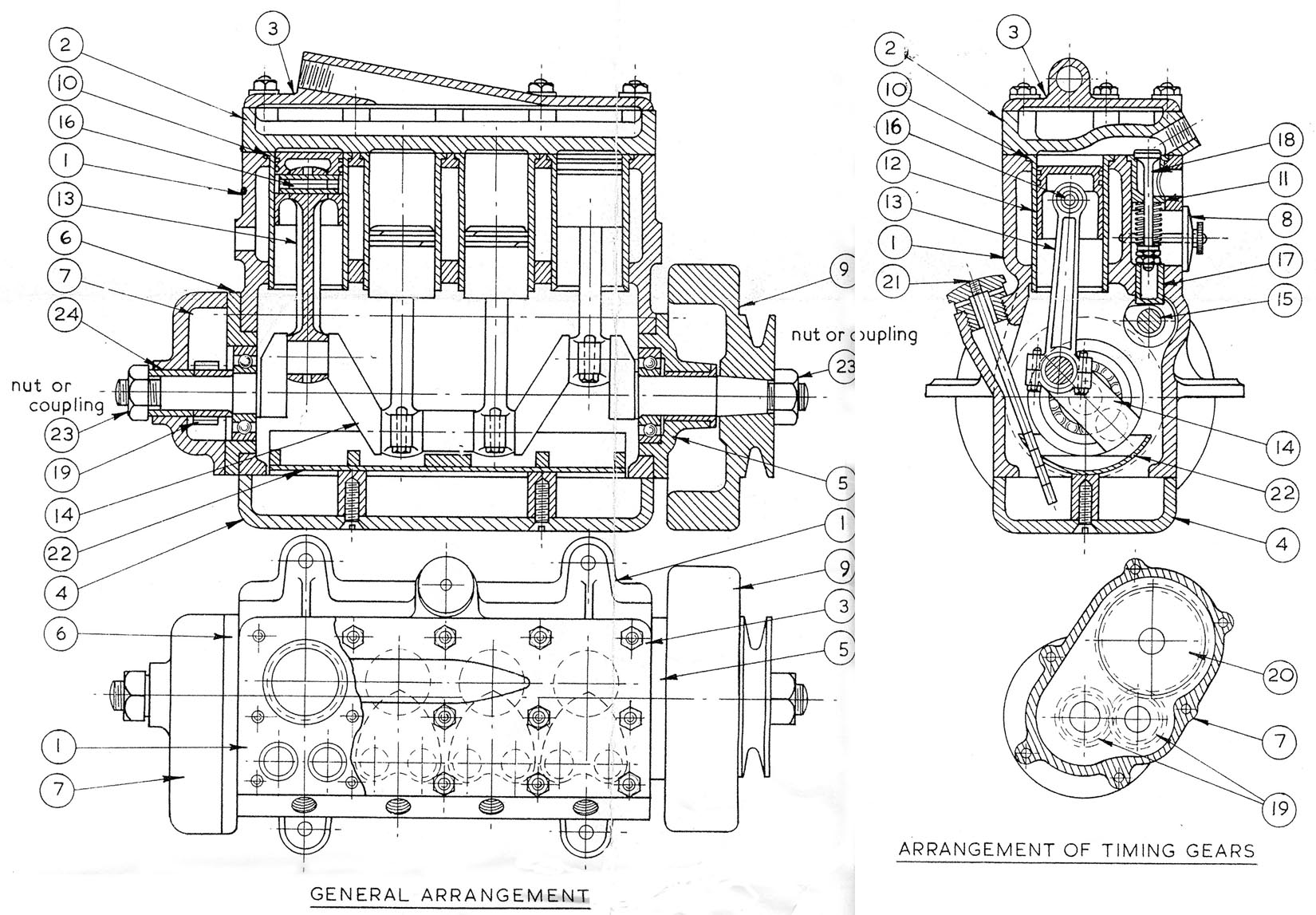
Seal Engine Cross Section Diagram
One of the early Seal engine cross-section diagrams that was used.
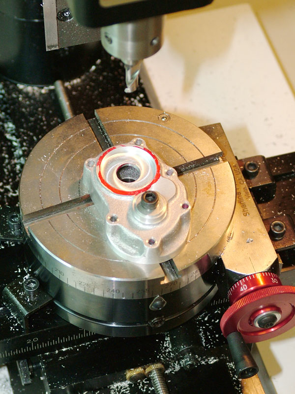
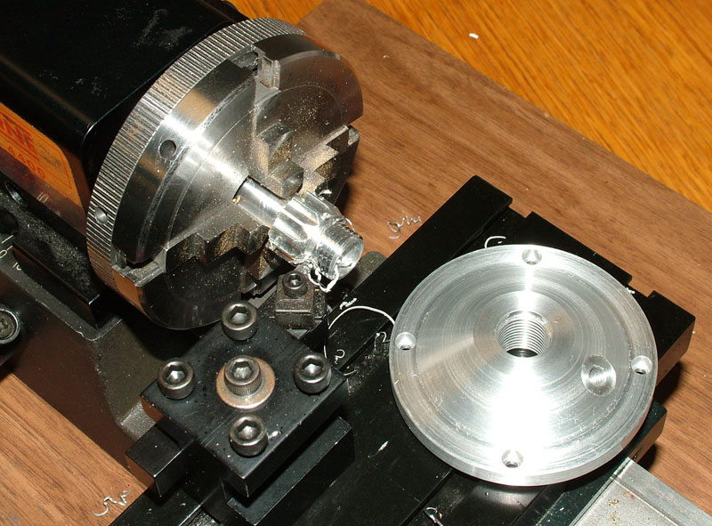
Seal Engine Timing Cover
The timing cover was machined flat, and the mounting holes were drilled using a rotary table.
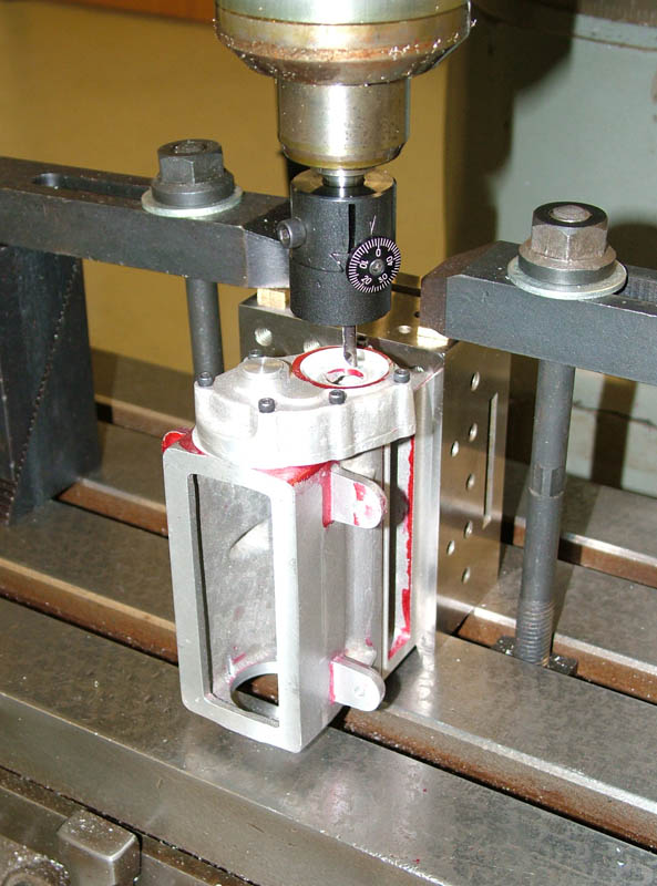
Seal Engine Block and Timing Cover
The timing cover holes were then transferred to the block. Once aligned, they were drilled and tapped. Then, the cam positioning hole was bored to size in the cover. (8/28/06)
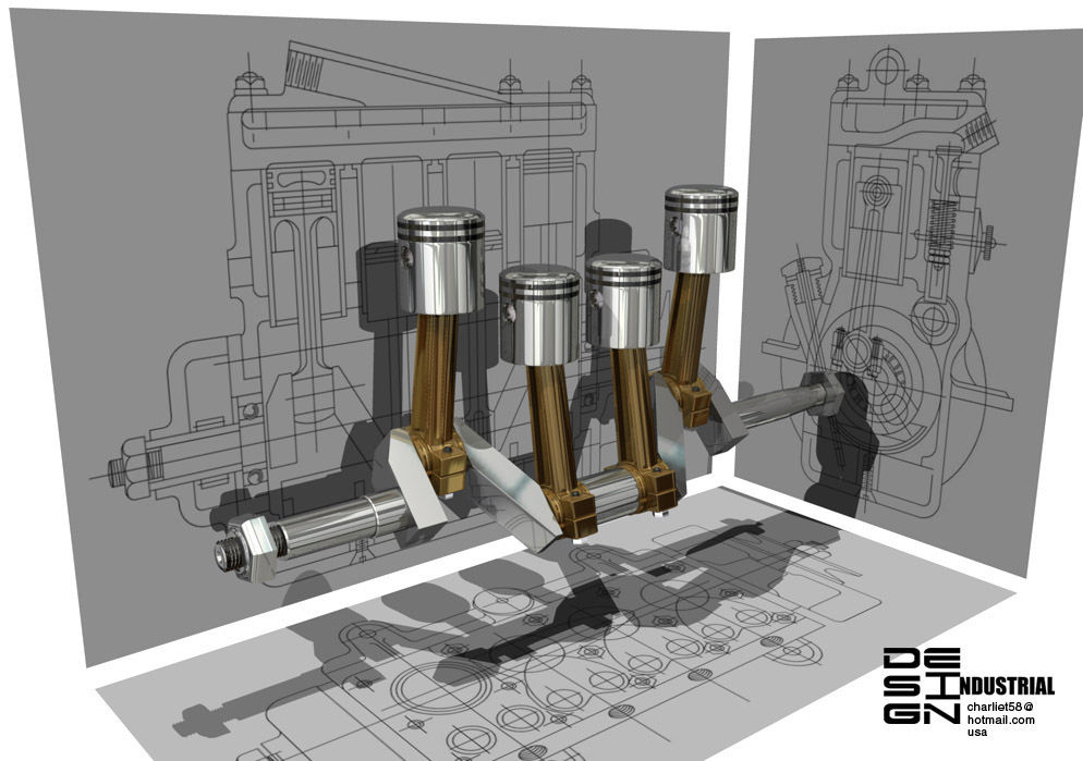
3D CAD Rendering
This 3D drawing shows the crankshaft, pistons, and rods. The CAD drawings for the Seal project were made by industrial designer Charlie Tomalesky.
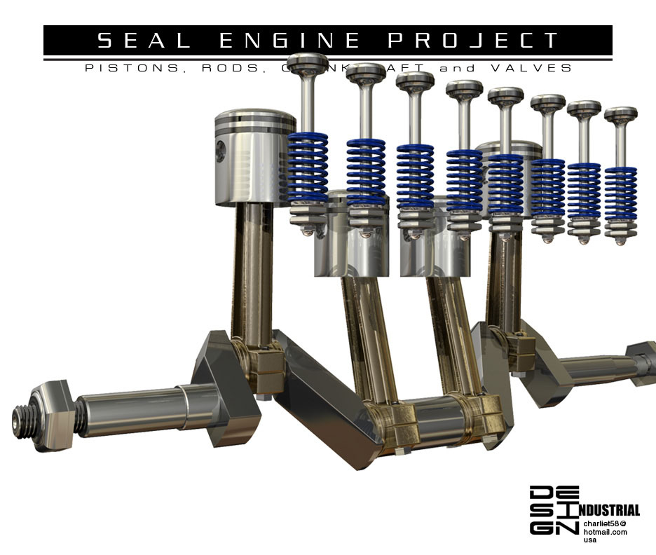
3D CAD Rendering
Another one of Charlie’s CAD drawings—this one adds the valves and valve springs to the driveline.
Seal Engine Progress—October, 2006
As of October 4, 2006 the block and manifolds were coming along nicely in the museum shop. Pam Weiss was at work on the camshaft and timing gear, and Joe Martin was testing a program to grind the cam lobes on a Sherline CNC milling machine.
A note from the build team: we modified the cam drawing to match the firing order published in the plans. It turns out that the drawing was correct, and the listed firing order was wrong. An old article in Model Engineer magazine, by engine designer Edgar Westbury, explained the error—but we learned of it too late. As a result, our firing order is actually different than what Edgar originally intended, but it runs fine.
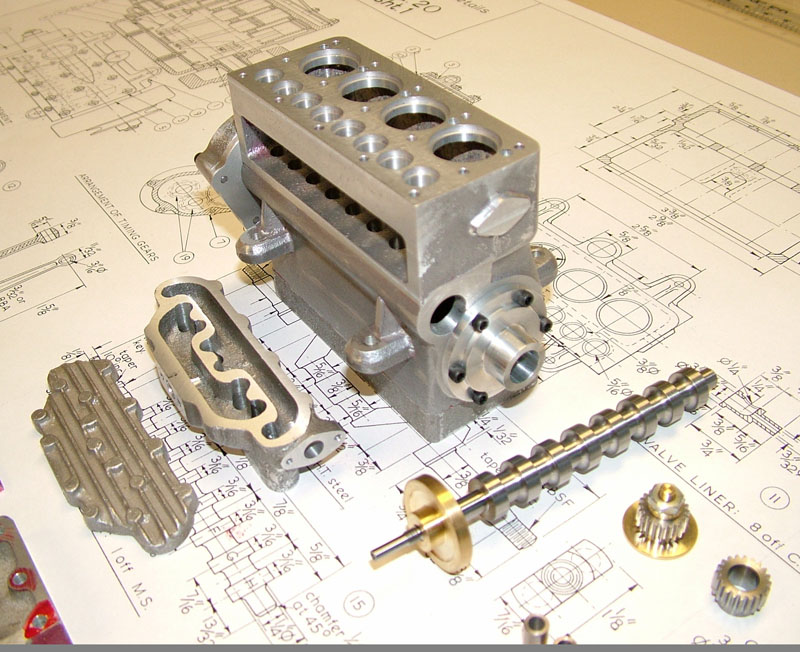
Seal Engine Progress
The Seal engine block and manifolds were coming along in October, 2006.
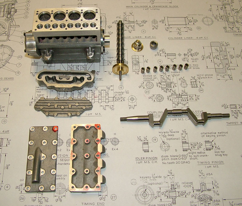
Seal Engine Progress
The components and block sit on top of the Seal plans.

3D CAD Rendering
Charlie Tomalesky made more drawings that incorporated the camshaft into the driveline.
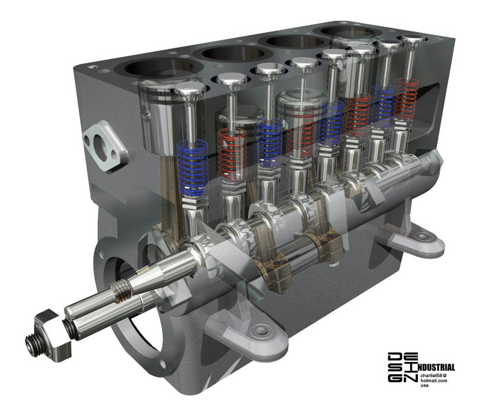
3D CAD Rendering
This drawing includes the block with a ghost view of the pistons, valves, crank, and cams inside. (10/16/06)

Seal Engine Components
Shown here are all of the parts that had been completed as of 10/25/06. Included are the cast parts that were machined by Tom Boyer, the bronze connecting rods made by Joe Martin, and Pam Weiss’ cam, valves, lifters, and lock nuts. Also, note the sandblasted aluminum engine stand that Tom machined.
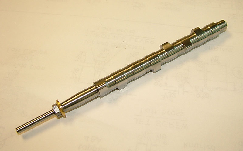
Seal Engine Cam
Joe’s CNC cam grinder worked! Pam Weiss’ cam blank was ground perfectly using Joe’s new CNC grinder.
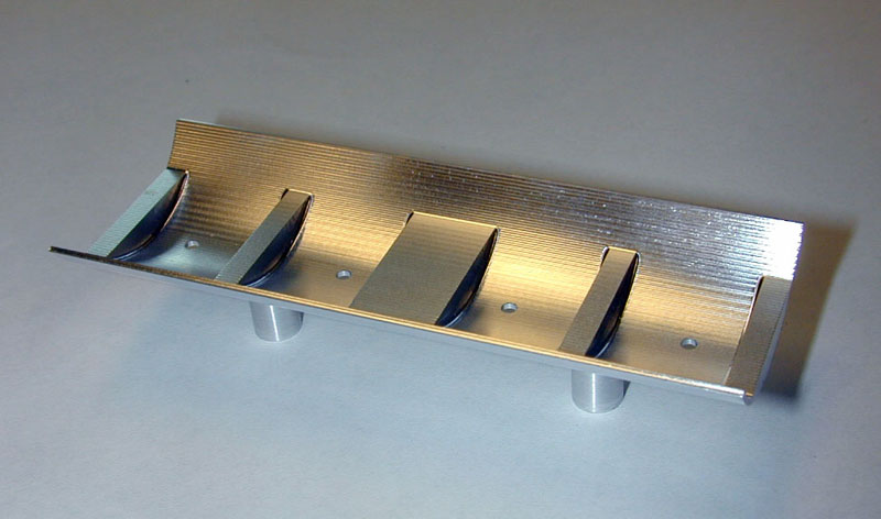
Aluminum Oil Pan
Ralph Cooney really outdid himself with his work for the Seal engine. The oil pan was made from a solid billet of aluminum using EDM (Electrical Discharge Machining) to vaporize the unwanted metal. The plans called for sheet metal with machined pieces fitted to it, and attached with screws. This is a much more elegant solution, but not many people have access to an EDM machine.

Brass Oil Pan
Ralph then made this second pan from brass using EDM. He said that the drawings by Charlie made the pan look so good in brass that he just had to make a second one.
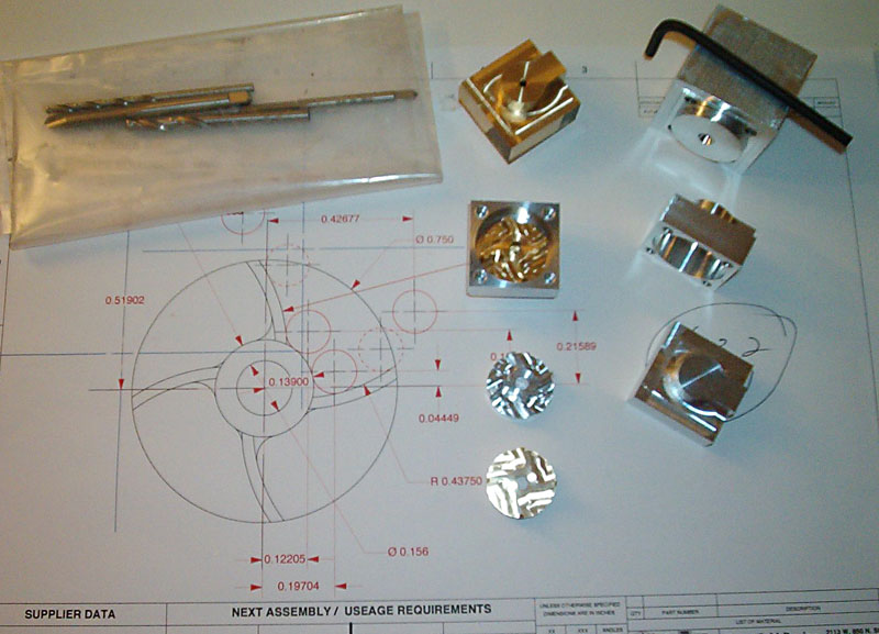
Water Pump Components
Robert Rosenfield seemed the natural choice for making the impeller and other water pump parts. Some of the unfinished parts for the water pump sit on Robert’s drawing. The aluminum impeller shown here was a test piece, as Robert was still cutting the final brass version.
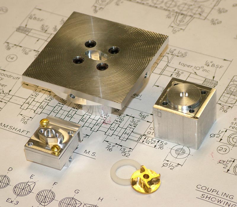
Water Pump Housing and Impeller
This photo shows the finished pump housing (lower left), and the brass impeller (lower right). The larger objects are fixtures that Robert used to make the parts.
Seal Engine Progress—November/December, 2006
3D CAD Rendering
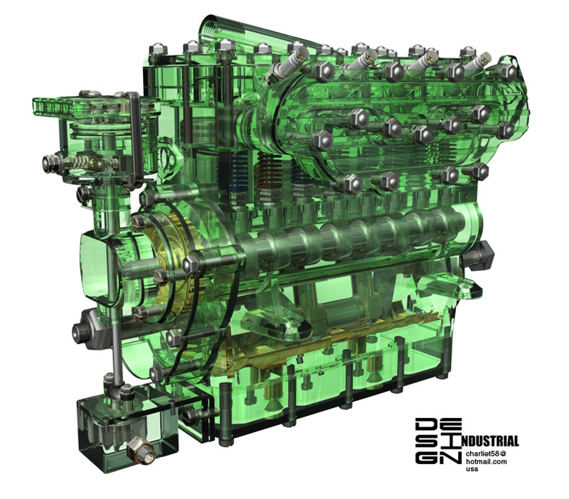
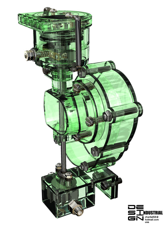
Charlie Tomalesky’s digital engine continued to gain detail. In this rendition, the pump and ignition system were added (11/8/06).
3D CAD Rendering
The 3D drawing was rendered so that internal components are visible.
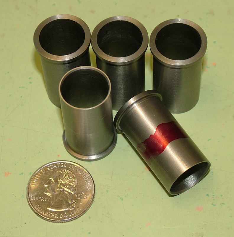
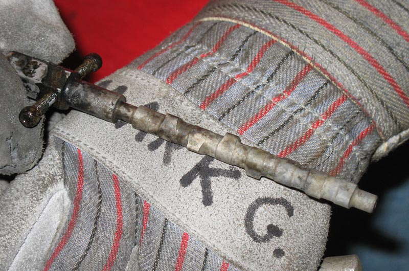
Cylinder Liners
The four cylinder liners, or sleeves, were machined by Tom Boyer, and then honed to exact size by Karl Rohlin. The 5th sleeve with a red mark was the setup part. On November 8, the sleeves were shipped to Australia on so that Ron Chernich could make the pistons, and fit the rings to the sleeves before returning them.

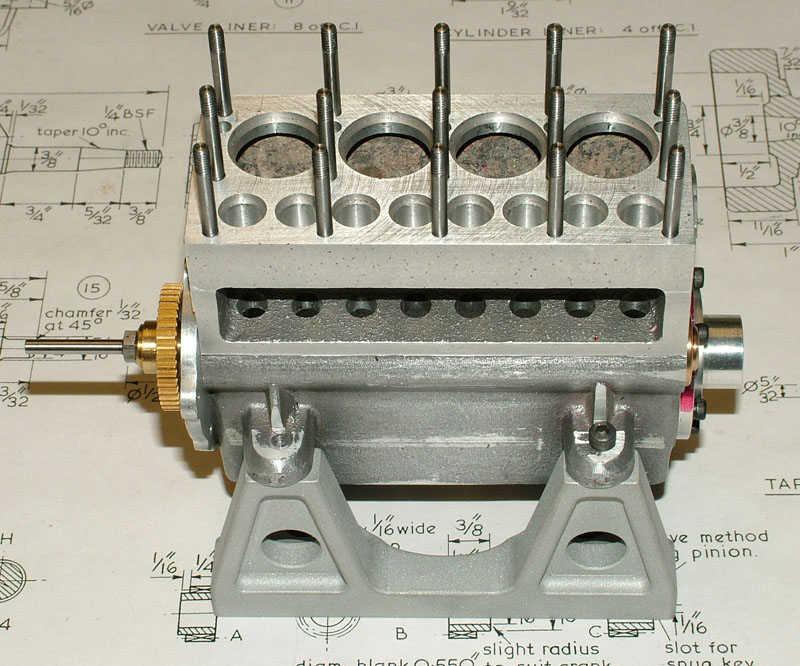
Seal Engine Progress
The Seal engine block with Pam Weiss’ head bolts in place—all fifteen of them. In the foreground are the two halves of the manifold, which Tom was still filing to match the edges. (11/21/06)
Joe Making Helical Gears
Joe Martin sitting in front of the Sherline CNC mill setup that he used to produce the helical gears for the distributor. Joe cut them in brass at first, and then made a few tweaks to the program and setup. He cut the final set in steel. In this photo, Joe is holding the finished set in his hand, and they came out great!

Helical Gears
A close-up of the two finished gears after heat treating, which gave them a darker color.

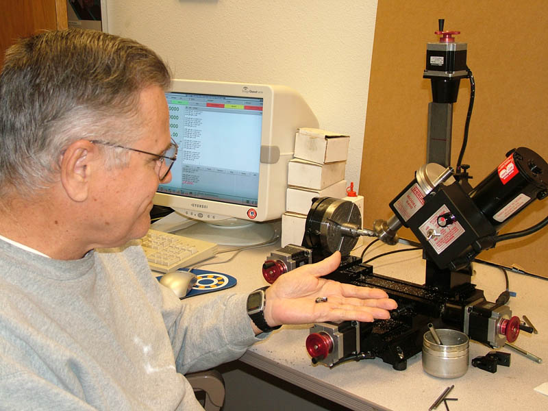
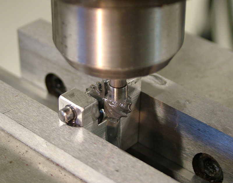
Lapping Gear Teeth
Tom Boyer lapping in the gear teeth with a diamond lapping compound. The milling machine spins the vertical gear as it meets the horizontal gear, which is held in a fixture. Lapping compound is applied to the spinning gears by means of a cotton swab.
Lapping Gear Teeth
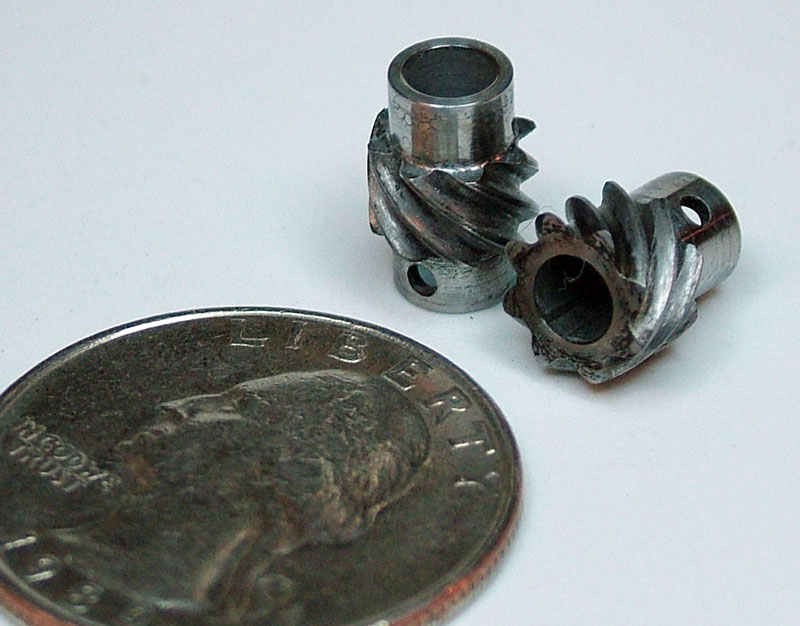
Helical Distributor Gears
The finished gear blanks after lapping. A US quarter provides scale reference.

Distributor Body and Cap
Frank Hoffman’s distributor body with the cap on.
Seal Engine Progress
The Seal engine block is shown with some of the completed parts. (12/05/06)
Seal Engine Progress
At this point, the camshaft was installed in the engine block.
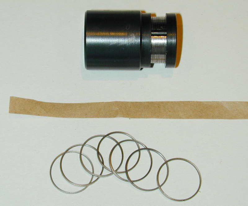
Piston Rings
Ron Chernich sent this photo from Australia showing a custom fixture and the piston rings ready for heat treatment. (12/6/06)
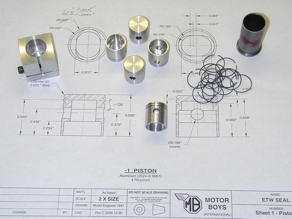
Pistons and Rings
Ron finished making the pistons and rings, and sent them back to the US for assembly. The finished pistons, rings, and fixtures are laid out on his drawing. (1/4/07)
Seal Engine Progress—January/February, 2007
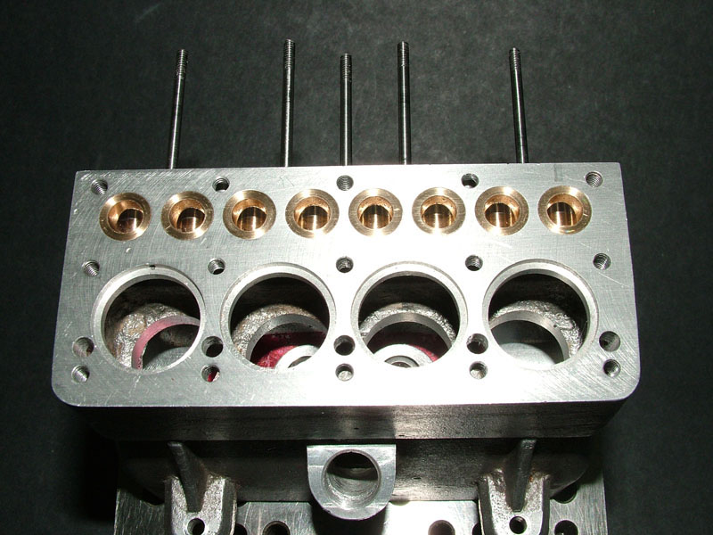
Seal Engine Progress
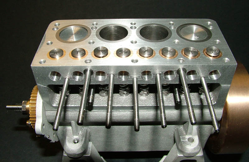
Tom finished and installed the bronze valve guides, and began working on the manifold studs. Unfortunately, a design fault in the engine causes two of the mounting studs that occur 90° from each other to line up. It’s amazing that a kit that has been out for over 60 years still hadn’t addressed this problem, but it’s still in the drawings that way.
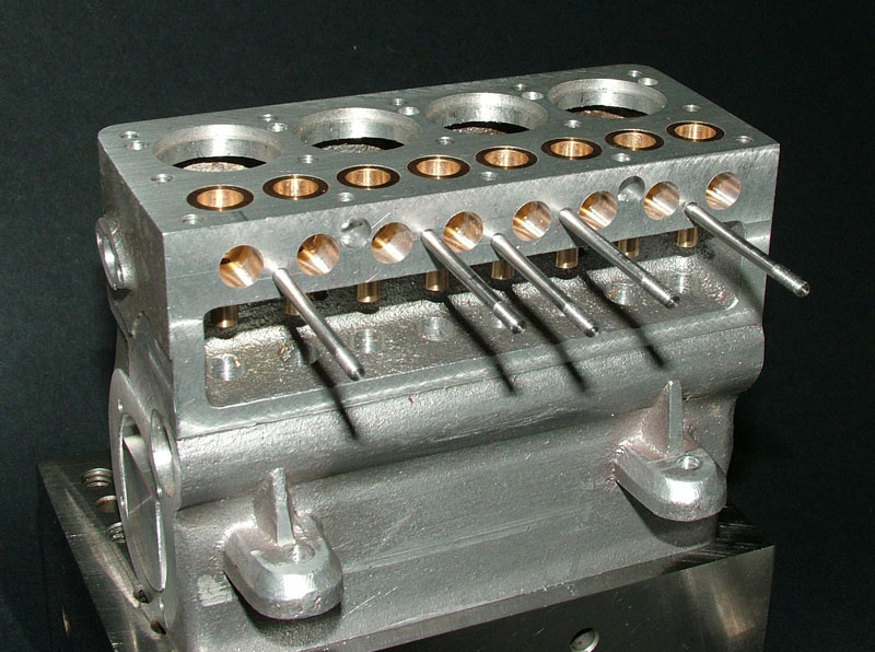
Seal Engine Progress
To adjust for the aforementioned design flaw, Tom used a tip from someone who had already built the engine. He ended up making an oversize base for two of the studs to overcome this problem. This put more threaded area in the minimum amount of depth available. That way sufficient torque could be put on the stud when mounting the manifold.

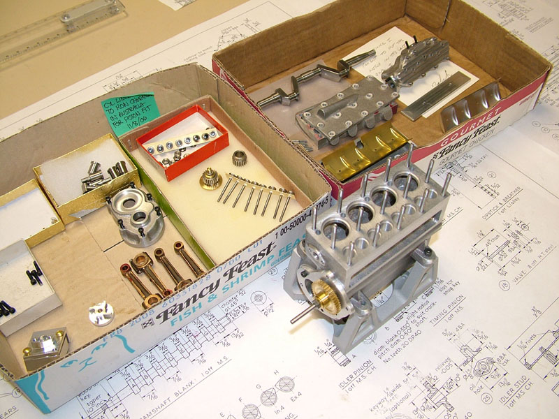
Seal Engine Components
Some of the beautifully made Seal engine parts await assembly. The project was really shaping up at this point. Some of the more difficult jobs—like making the distributor, carburetor, and doing final assembly—were getting underway. However, with the talented group assembled for this project, we were always confident that any obstacle could be overcome.
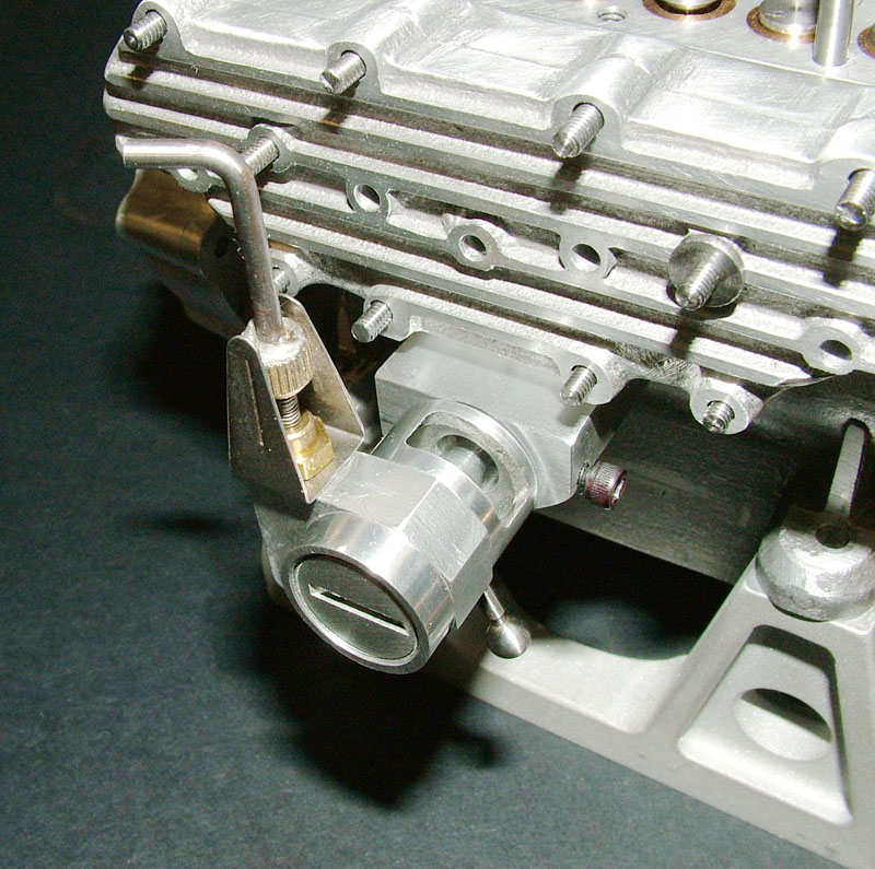
Seal Engine Carburetor
The M&H Variable Venturi carburetor was designed by Joe Martin and Carl Hammons years ago for use on radio controlled model engines. The adjustable Venturi will make it easier to tune and run this engine than the original carburetor designed in 1947. We had to put Jim Clark’s stock carb build on hold until we could test the Venturi out. (2/20/07)
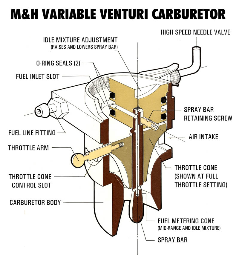
M&H Carburetor Drawing
This drawing shows how the M&H carburetor works. Unfortunately, the original plan drawings were lost many years ago. All that remains are some cutaways drawn by Craig Libuse in the 1980’s.
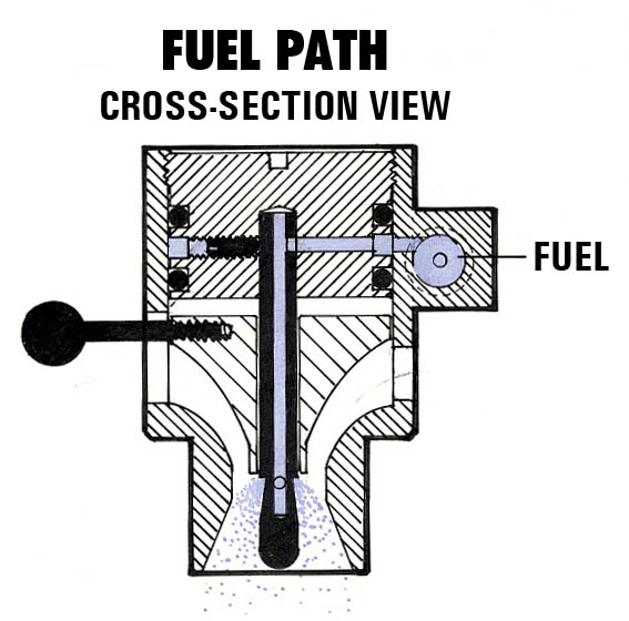
M&H Carburetor Drawing
Brass Oil Dipstick
Karl Rohlin’s sons, Taylor and Dakota, did a nice job on the brass oil dipstick. Here it is ready to thread into the block.
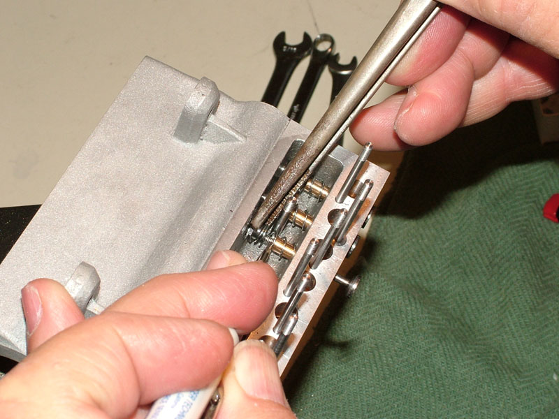
Seal Engine Progress
Tom Boyer installs the valve springs and adjusting nuts as the eight valves go into the block.
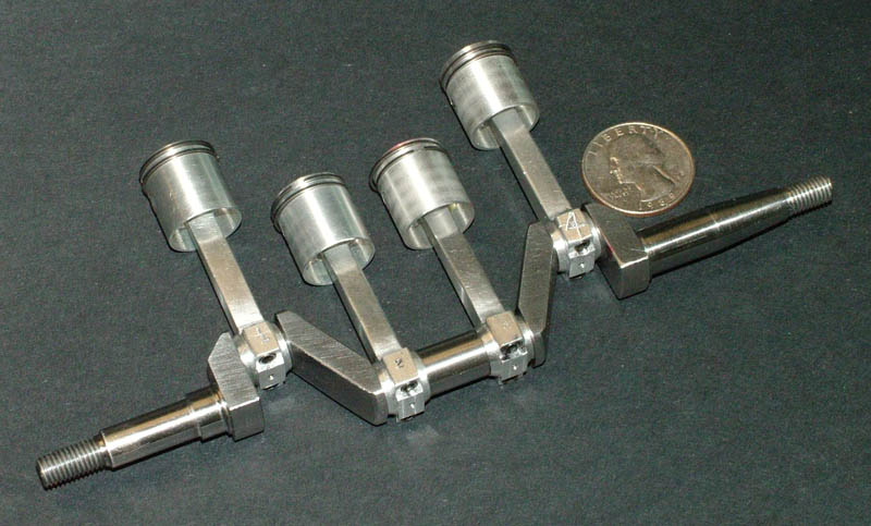
Crankshaft Progress
The pistons and rods are assembled to the crankshaft.

Seal Engine Progress
The crank and pistons are installed in the block. One ring broke during assembly, but fortunately Ron supplies an extra piston with rings—so we had a spare!
Seal Engine Progress
The assembled short block ready for a test run.
First Test Run-In —(3/28/07)
On March 28, 2007 we did our first run-in of the Seal engine, with the short block being run using a Sherline lathe as the drive. Tom filled the crankcase with mineral oil, and we took a video of the motor being run at low rpm. By running it for a short period we were able to break in the wear surfaces, and make sure that everything ran freely. As you can see in a second video, it spins fine!
Seal Engine Progress—April/May, 2007

Heat Treating the Camshaft
On April 13, 2007, Pam Weiss and Tom Boyer heat treated the cam to case harden it. Larry Simon documented the process. They used the heat treating oven at Sherline to heat the cam in a crucible filled with Casenite.
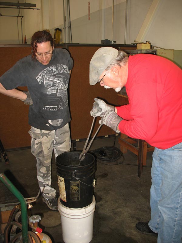
Heat Treating the Camshaft
Then they cooled it down in a bucket of water. Two cams had been ground, but the heat treating process put a slight bow in both. When trying to straighten the first cam, it broke due to brittleness after hardening.
Heat Treating the Camshaft
We decided to simply leave a slight bow in the second one, rather than breaking both. The slight variation in valve lift due to the warping would not have a major effect on the running of the engine.
Heat Treating the Camshaft
The finished camshaft after heat treating.
Seal Engine Progress
By May 10, 2007, the engine was nearly completed. It just needed the working parts of the distributor and spark plug leads.
Seal Engine Progress
Joe was also considering whether to replace the water pump with an oil pump.

Seal Engine Progress
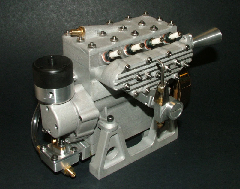
A top view of the engine shows the stinger exhaust pipe that Tom designed and turned from aluminum.

Seal Engine Progress
This angle shows the M&H carburetor, designed by Joe in the 1970’s for model aircraft engine use. It features a variable Venturi of Joe’s design.
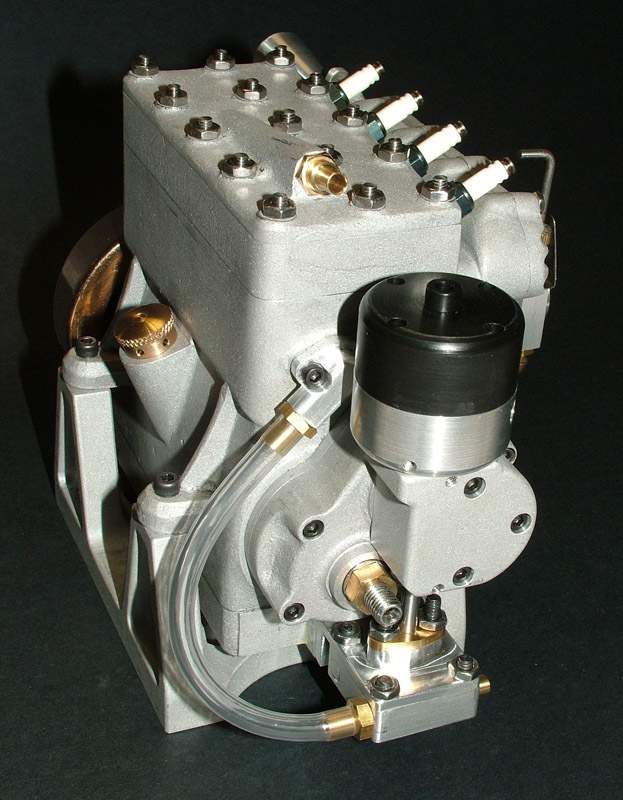
Seal Engine Progress
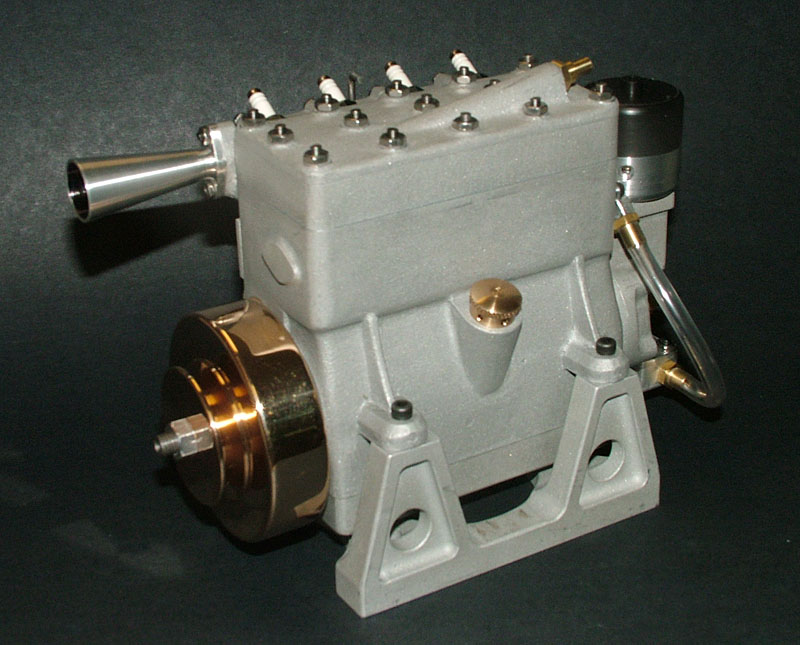
The front of the Seal engine with distributor in place, and water pump installed and plumbed.
Seal Engine Progress—June/July, 2007
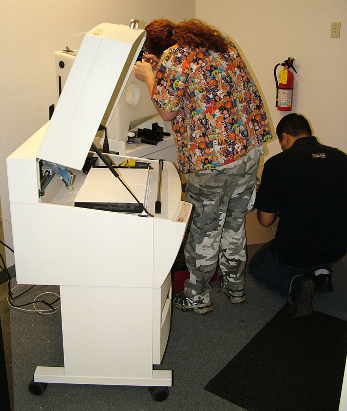
Working With the 3D Printer
One of the newer additions to the museum shop was a Z-corp 310 3D printer, capable of rapid prototyping. We hoped to be able to take plans from 3D scans or drawings, and produce cast engine blocks and other kit parts that are no longer available. In this photo, Pam Weiss and Saul Hernandez hook up the machine for a test run.
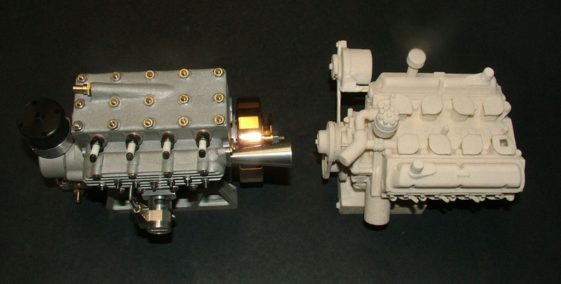
Seal Engine and 3D Printed V-8
The Seal engine sits on the left, and on the right is a sample model V-8 produced with the 3D printer.
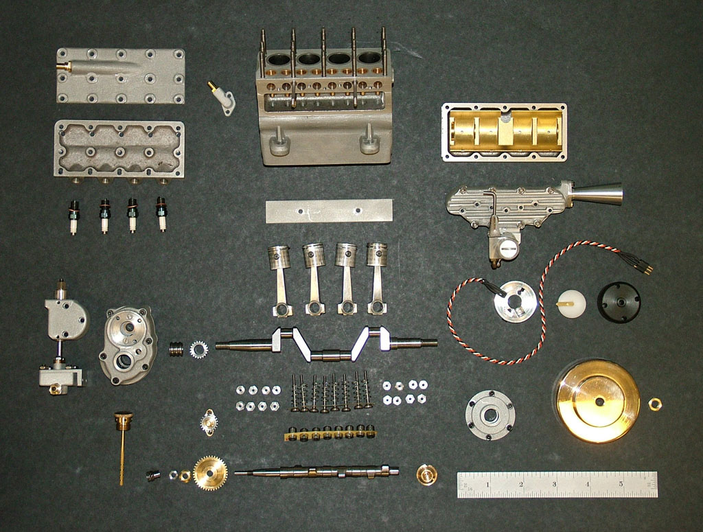
Disassembled Seal Engine
All of the Seal engine components as of June 6, 2007. Tom had to take the engine apart anyway, so we laid out all of the significant parts for a photo. After the engine was buttoned up for the final time, most of the fine work done on these parts has been covered up.
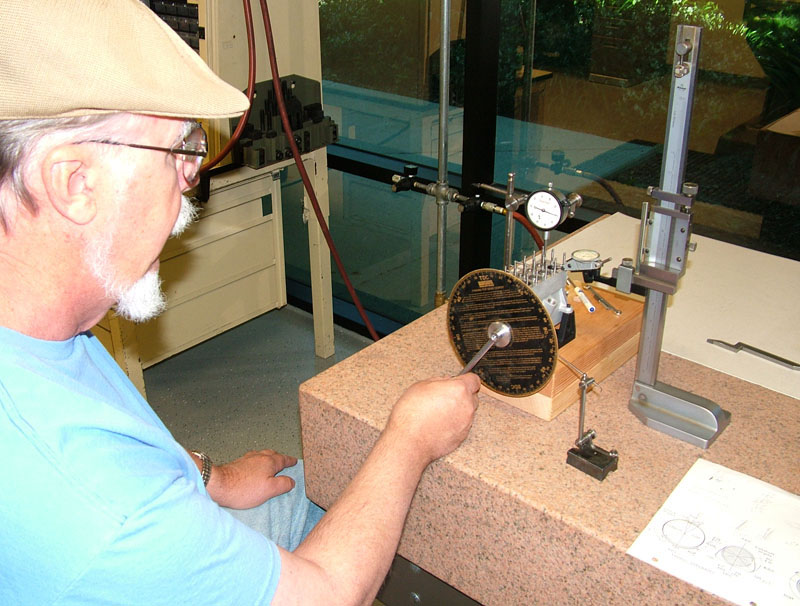
Final Assembly
During final assembly, Tom set the valve timing. A degree wheel is fixed to the flywheel. A dial indicator shows when the #1 piston is at Top Dead Center (TDC).
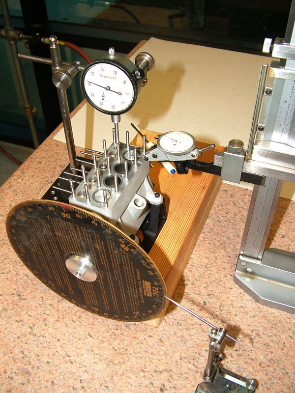
Final Assembly
A pointer is set to the TDC mark on the degree wheel. Then the engine is turned over, and the cam is adjusted so the first valve is fully open at 250°. A second indicator on the valve shows when it is fully open.

Seal Engine Test
On Saturday, July 7, 2007, Duarte Cabral stopped by to help Tom and Joe confirm that the design and timing of the ignition was good to go. After several checks, everyone agreed that there was a good spark. At this point, the engine had compression and spark at the plugs. As long as we could get fuel into the cylinders, we were confident that the engine would run. Tom started working on the gas tank
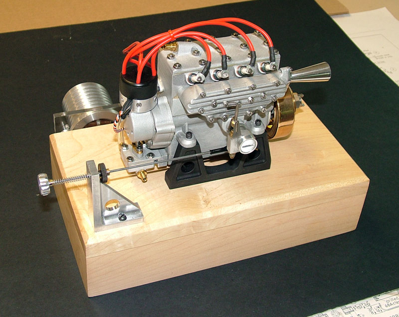
Seal Engine
As of July 18, 2007, the engine was mounted on a new (temporary) maple base. Tom made and mounted a spring-loaded throttle arm that includes a dial idle adjustment. On the back, Duarte’s ignition module is now housed inside a machined, finned aluminum canister.
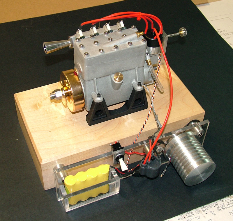
Seal Engine
Eventually some of these components would be hidden underneath the final display base, but for the first run they are exposed—in case they need to be accessed. Tom was finishing up the fuel tank and lines. The project was almost fully complete!
First Pop!—July 21, 2007

Tom Boyer With the Seal Engine
Tom is nervous but ready for the first pop. All of the hard work put in by our group of craftsmen would come down to this.
Seal Engine Prep
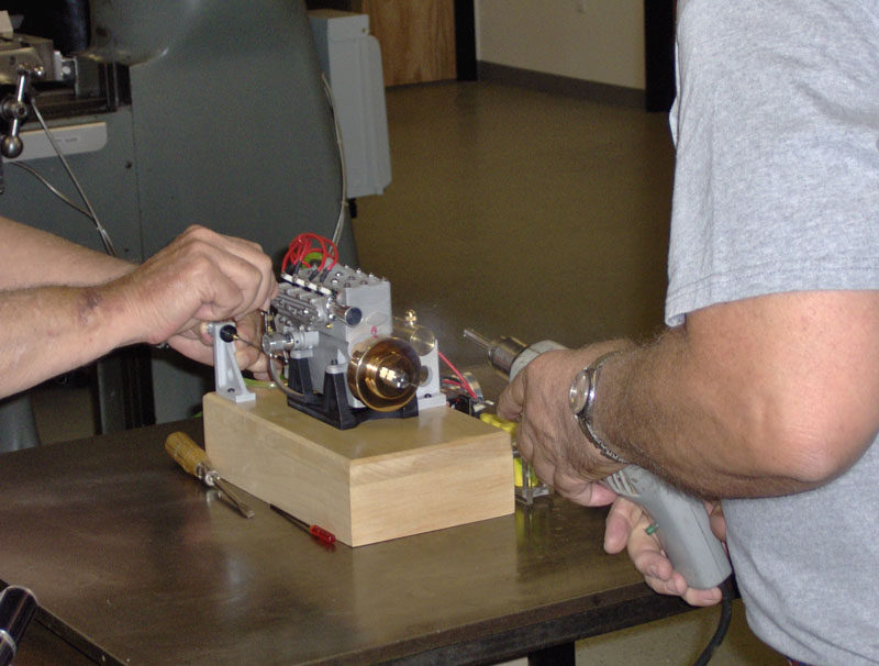
10:44 AM: Joe readies the Seal engine.
Seal Engine Prep
Tom engages the drill motor, and the engine is ready to go.
Seal Engine First Pop
Scott Wolf captured the first firing of the engine. With the starter drill removed, it was puffing away on its own, sounding much like a little Offenhauser. On the first and second tries, it ran for about 5 seconds. From there on things went downhill, and everything we tried seemed to make it worse.
Close, but No Cigar
We had Champagne chilled and waiting, but never got to open it. There was still more work to be done before we had a smooth running engine. Anyone who has tried building an internal combustion engine from scratch will probably not be surprised by this. However, a word of congratulations should go out to all those who participated in this project. No parts failed, and they all fit together well. From this point on it was just fine tuning. Watch video of the first, second, and third pop.
Seal Engine Full Run—August 8, 2007
Finally, the Seal engine is a success! Within a week or so of the first pop, Joe and Tom got the kinks worked out. They had to clean and re-gap the spark plugs, raise the gas tank, and make a few other minor adjustments. The final result is a strong running Seal engine. Tom fired up the engine for this video of the full run. It now starts with a twist of the flywheel, idles at less than 1,000 rpm, and revs freely. The Seal engine does pass a little oil, but this is normal because there are two compression rings on the pistons, but no oil rings.
Joe and Tom would continue to refine the fuel system to improve performance throughout the rev range. Craig also built a more appropriate base for display in the museum, and designed a plaque to honor all those who contributed parts.
What next? After finishing the Seal engine build, we were ready to move on to the next museum shop project. Once again, this project would be a group build. Ultimately, we chose to build and document a Howell V-4 IC engine as the second Craftsmanship Museum shop project.
Post-Completion Engine Updates

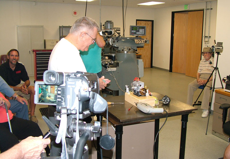
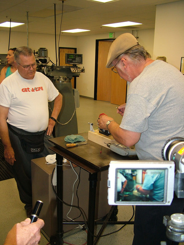
Tom demonstrating the Seal engine for a hotrod club from Fallbrook, CA in December, 2008.
After many demonstrations, the engine now has several hours of running time on it—mostly in 1-3 minute runs. In mid-November, 2007 the engine seized while Tom was test running it. The rod on the #1 cylinder galled the crankshaft, causing the engine to stop. Fortunately, no other damage was done.
Tom disassembled the engine, cleaned and polished the crankshaft journals, and did the same for the rod bearing surfaces. The galling was insignificant enough that it could be polished out. It was determined that the small hole on the bottom of the rod cap, which splashes in the crankcase oil, was not getting enough lubrication to the rod journals on the crankshaft. The holes would be enlarged slightly, and a lip was milled into the cap. That would help to capture additional oil and force it into the hole.
We also considered making an oil groove around the inside of the rod cap, and drilling an additional hole from the top of the rod to bring in more oil. Along with that, we decided to drill eight small holes under the oil ring through the piston walls. Those holes, and a knife edge on the bottom of the piston sleeve, would hopefully help remove excess oil from the cylinder wall. (10/24/07)
As of January, 2009, the Seal engine had run over a gallon of gas through the carburetor. It was smoking less and running better each time as the rings seated. Tom was happy to fire up the engine for a demo run for any and all visitors to the museum.
Seal Engine Update—February 6, 2009

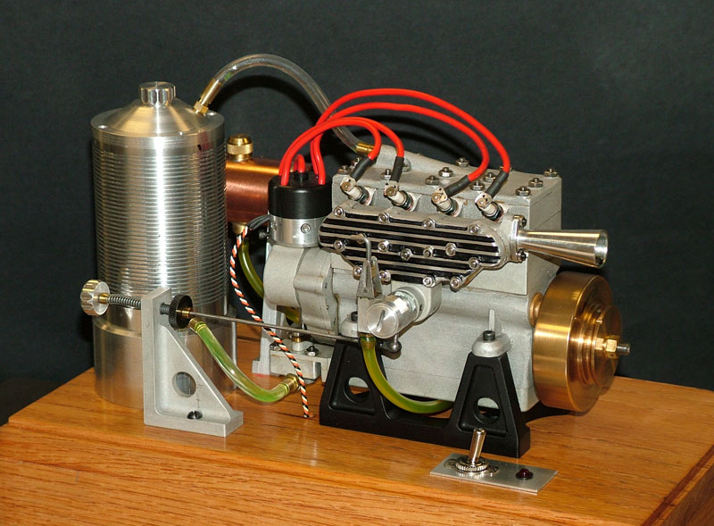
Seal Engine
To eliminate the separate water tank, and keep everything mounted to one base, Tom created a finned aluminum water cooling tank. The tank mounts to the engine base. The on/off switch has been relocated to make room for it.
Seal Engine
Filler Cap Machining
In this photo, the 1/2-20 filler cap is being threaded. A Sherline lathe was used to cut the male thread.
Filler Cap Machining
The 1/2-20 thread in the lid of the tank was tapped.
We thank all of the craftsmen involved in the Seal engine build for contributing to this rewarding project. It was truly a group effort, and the build team should be proud of this fine running Seal engine. To learn about our second museum shop project, visit our page for the Howell V-4 build.