The Howell V-4 Engine Project—Full Build
Below we have documented the Joe Martin Foundation Howell V-4 engine build from start to finish. Photos and descriptions of the components illustrate the unique collective craftsmanship—with a beautiful final result.
Jerry Howell’s Prototype V-4 Engine
Jerry Howell’s V-4 Engine
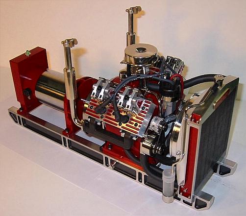
This is what our build team was shooting for. Jerry’s finished V-4 is a thing of beauty, and we were eager to try to replicate it. Compared to the previous photos of Jerry’s V-4, these show the longer rails (cut on a Sherline CNC mill) and generator at the end of the engine.
Jerry Howell’s V-4 Engine
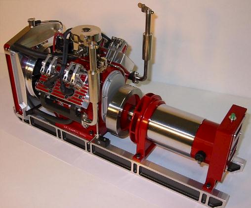
Mounted on the end of the generator is a small LED engine hour meter. Jerry also made some tilting covers to keep rain out of the vertical exhaust pipes.
Jerry Howell’s V-4 Engine

Jerry Howell’s V-4 Engine

Jerry Howell’s V-4 Engine
Howell V-4 Project Starts (9/19/07)
Aluminum Block
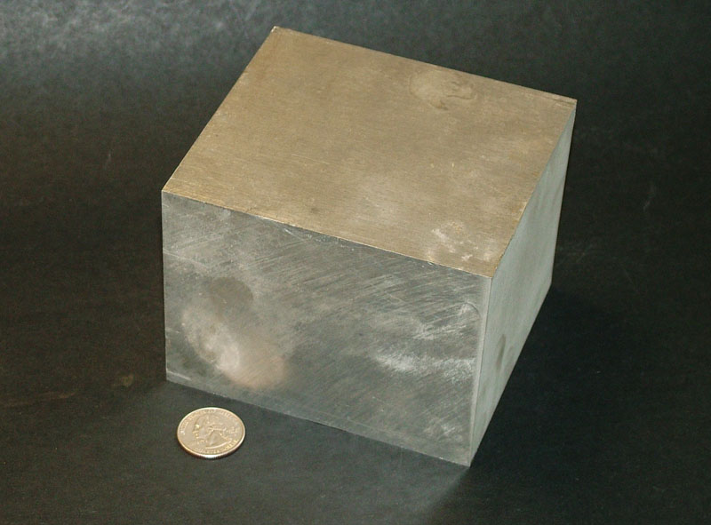
You have to start somewhere. This is the block of 7075 aluminum that Pam Weiss cut on Sherline’s Flow waterjet. A US quarter provides scale reference. This would eventually become the engine block for the V-4.
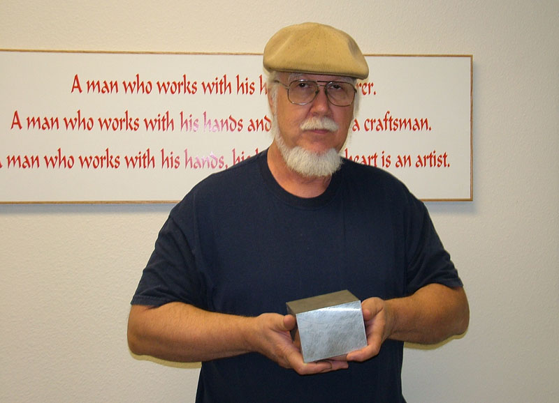
Tom With the V-4 Billet
Tom holding up the blank aluminum block. With time, this plain block would begin to transform into a full-blown internal combustion engine.
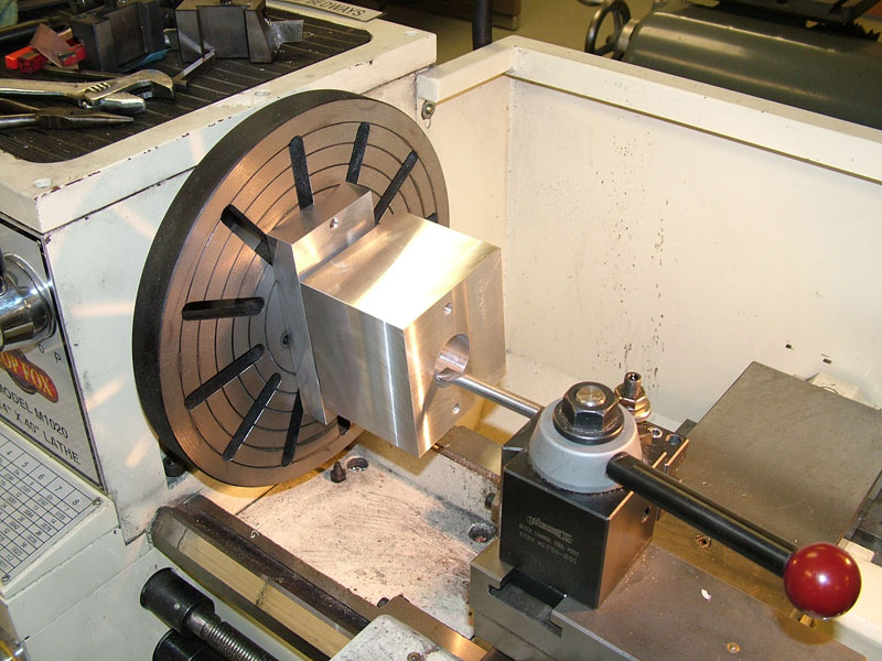
Boring the Crankshaft Hole
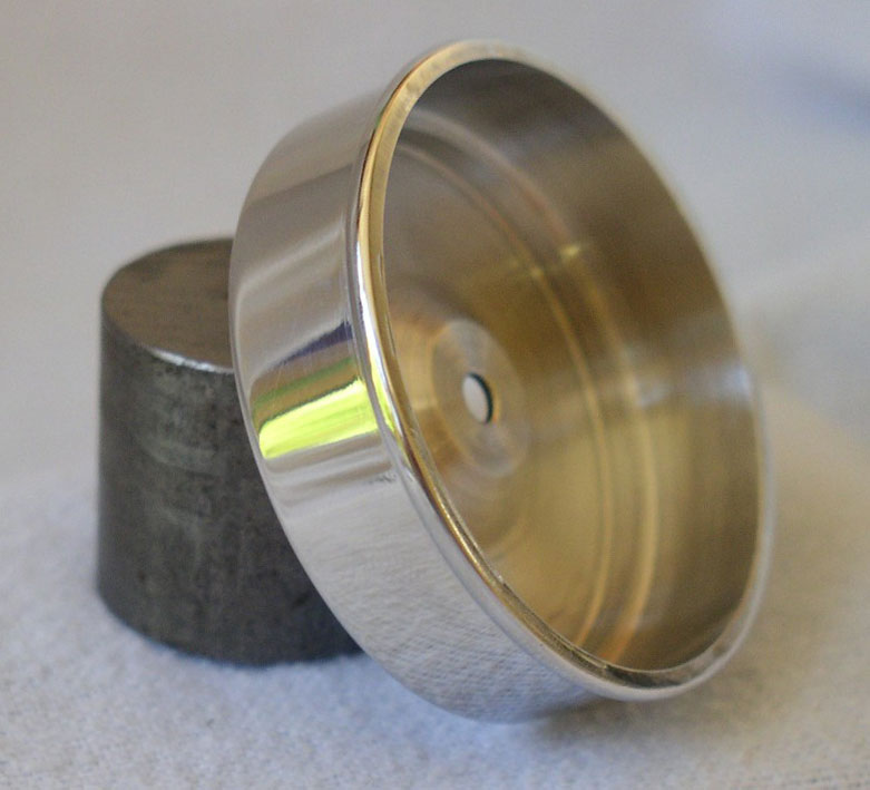
The aluminum billet has been squared up to size. The block was bolted to a fixture on a faceplate while the crankshaft hole was bored. (9/25/07)
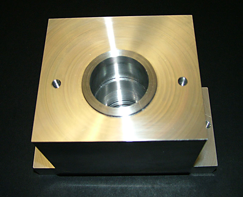
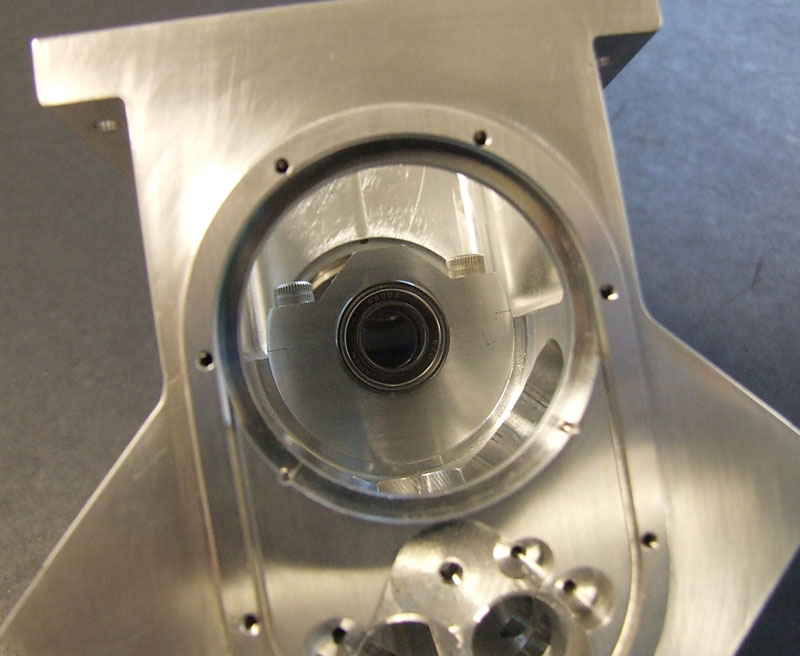
Boring the Crankshaft Hole
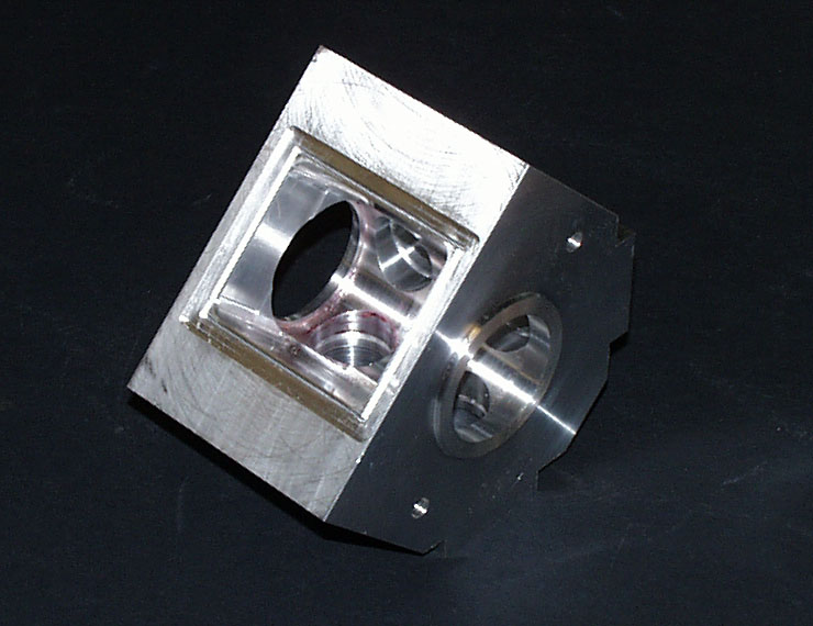
This photo shows the other side of the block after the flange on the second side had been turned. The two internal counter bores have also been added.
Howell V-4 Engine Progress—October/November, 2007
Howell V-4 Engine Block
One of the surfaces for the head was cut smooth with an end mill, and then finished with a fly cutter. (10/4/07)
Howell V-4 Engine Block
The cylinder holes on the first side are drilled to make a clearance hole for the boring tool.
Howell V-4 Engine Block
A boring tool brings the cylinder holes to size. (10/5/07)
Howell V-4 Engine Block
Both cylinder holes on the first bank are completed. The scribed line in red Dychem shows where the second face will be machined for cylinders 3 and 4.
Howell V-4 Engine Block
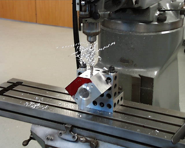
Tom machined the second cylinder head flat. The block is beginning to take on the V shape. A drill was set to make clearance holes before boring the second bank of cylinder holes. (10/9/07)
Howell V-4 Engine Block
A boring bar opens up the second bank of cylinder holes to exact size.
Howell V-4 Engine Block
The engine block with all four cylinder holes bored.
Howell V-4 Engine Block
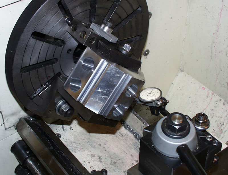
The block was mounted to a large faceplate on the lathe, and a dial indicator was used to find the center of the cylinder holes. (10/19/07)
Howell V-4 Engine Block
The block was removed from the faceplate after each cylinder hole was counterbored.
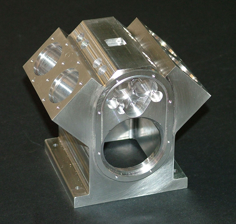
Howell V-4 Engine Block
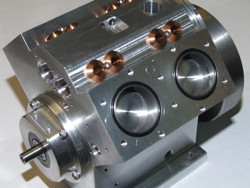
The bottom of the block as of late November shows access to the crankcase. At this point, about half of the original material had been removed.

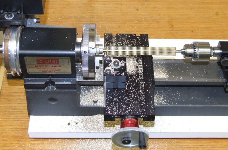
Cam Gear Progress
A Sherline mill was setup to open up the five lightening holes called for in the intermediate cam gear. The holes were drilled first. Then, this 3/8” end mill was used to true them up. The plans for the part can be seen in the background.
Howell V-4 Engine Progress—December, 2007

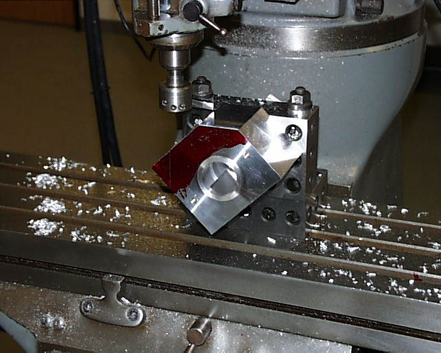
Howell V-4 Progress
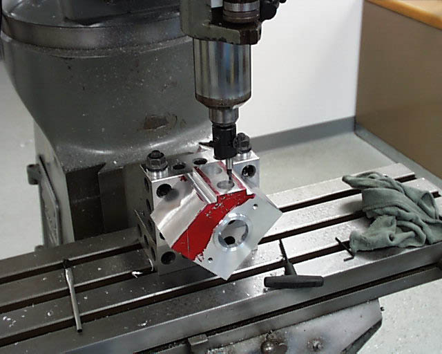
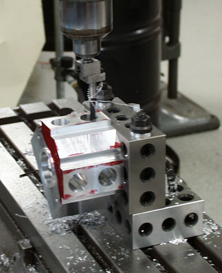
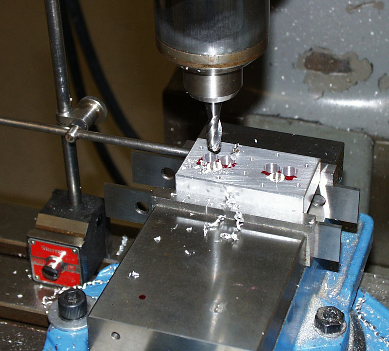
Machining the spark plug hole and counterbore at a compound angle. The silver vise was held at a 12° while the head on the mill was tilted to 8°. (12/26/07)
Howell V-4 Progress
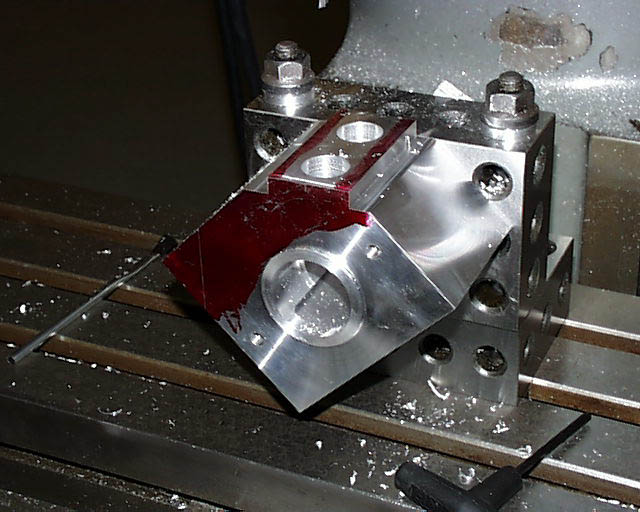
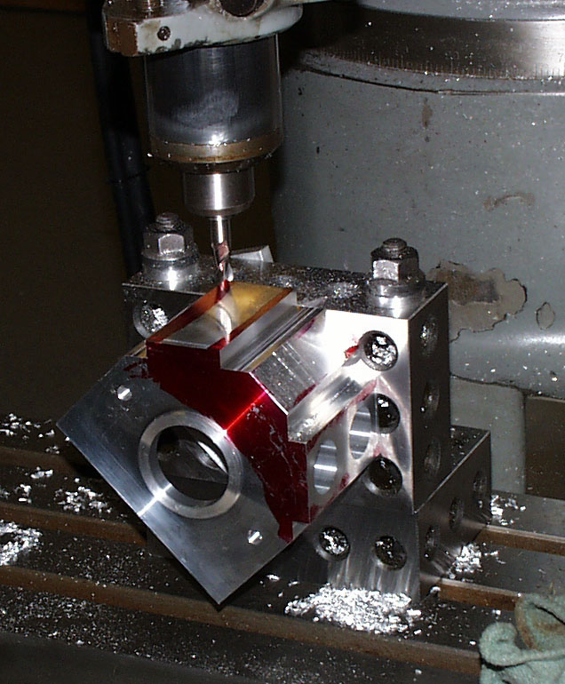
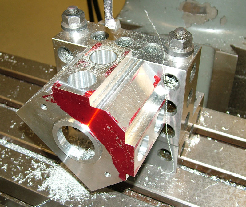
Tom used a ball end mill to form part of the combustion chamber.

Howell V-4 Progress
Another angle of the ball end mill work.

Howell V-4 Progress
The top side of the head with spark plugs inserted.
Howell V-4 Progress
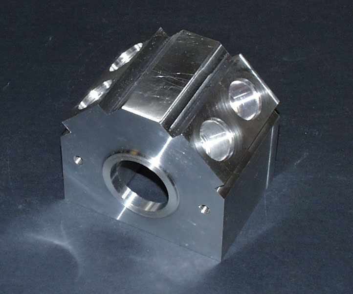
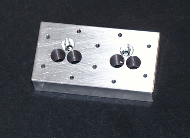
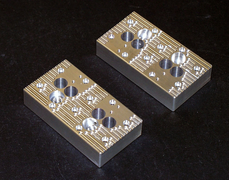
The bottom side of the head. There are two pairs of holes for the valves, with the spark plug holes nestled between them.
Howell V-4 Engine Progress—January, 2008
Machining Cooling Slots
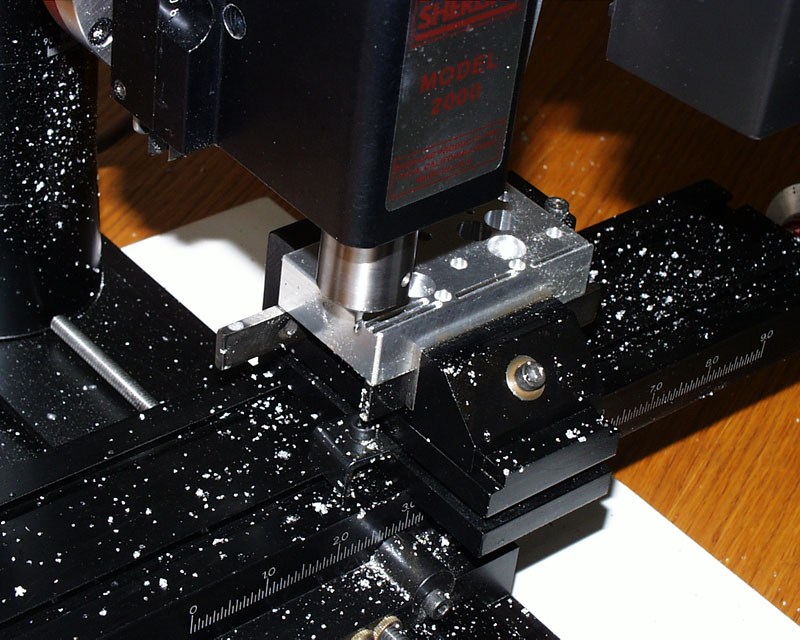
A small end mill was used on the Sherline mill to cut cooling slots in the top of the head. (1/3/08)
Machining Cooling Slots
The two heads with cooling slots cut out.
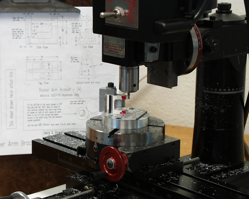
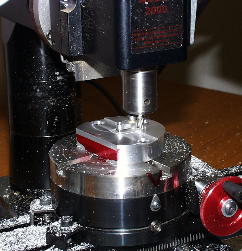
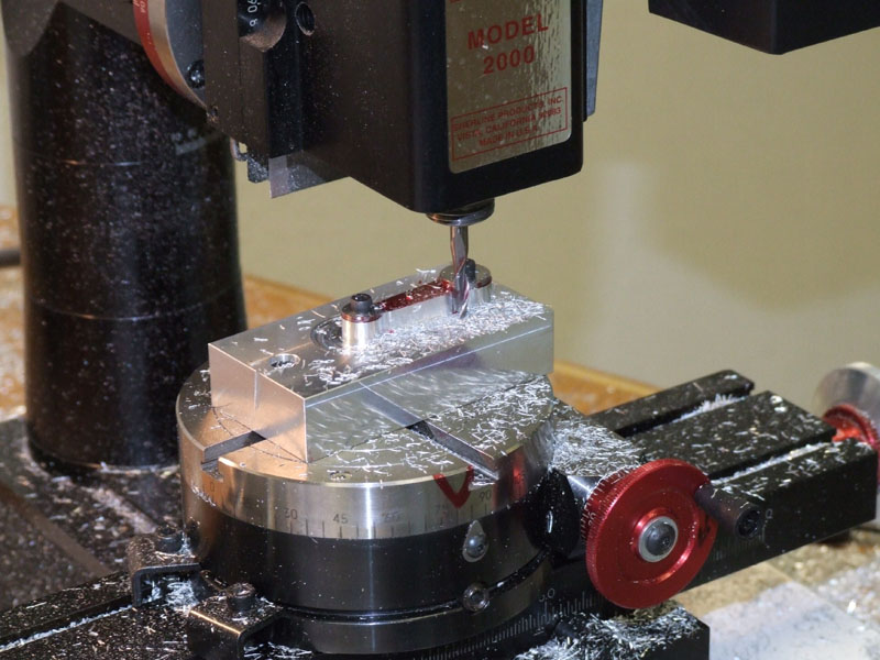
Machining Rocker Arm Brackets
The mill was set up to cut the radius on the end of the rocker arm brackets using a rotary table. (1/10/07)

Machining Rocker Arm Brackets
Note the special clamp that Tom made to hold the brackets during machining.
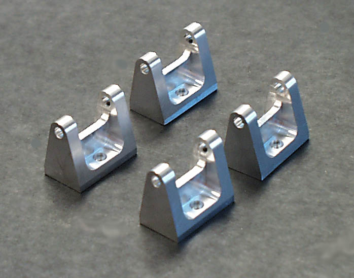
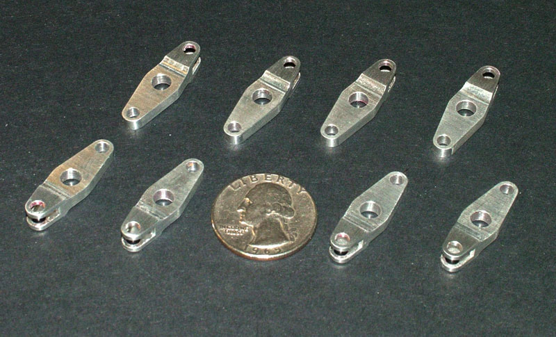
Rocker Arm Brackets
The finished rocker arm brackets. The machining marks were removed with a couple of passes over a stone, or piece of fine sandpaper. Doing so on a flat surface allows the part to transition smoothly from flat sides into the radius.
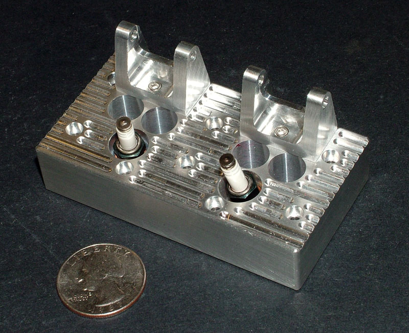
Howell V-4 Head Progress
One of the heads is shown here with rocker arm brackets and spark plugs installed. (1/24/08)
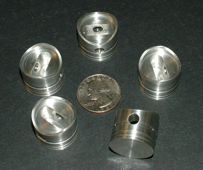
Howell V-4 Pistons
Bob Seigelkoff made these five aluminum pistons. As we found out in our Seal engine build, it’s always good to have a spare.
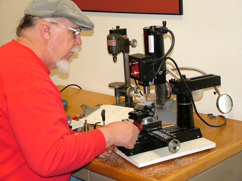
Machining the Distributor Drive Housing
Tom Boyer machines a round boss on the distributor drive housing/camshaft end cover. He used a rotary table on the Sherline mill.
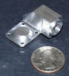
Distributor Drive Housing
The finished distributor drive housing and camshaft end cover before the parts were split. (1/30/08)
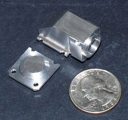
Distributor Drive Housing
Here the two parts are split. The two halves would be installed separately but side-by-side on the finished engine, using two common bolts in the center.
Howell V-4 Engine Progress—February, 2008
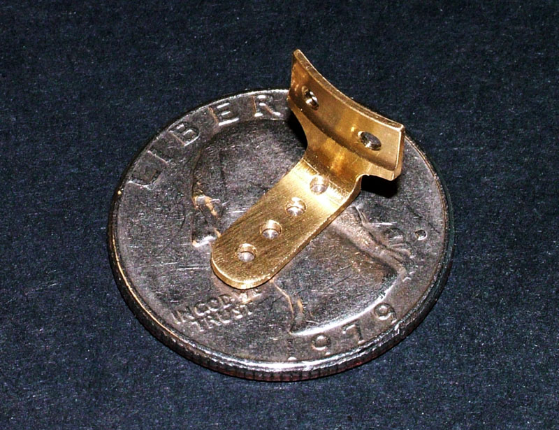
Distributor Spark Advance Arm
The distributor spark advance arm was milled from a solid piece of brass. The curve in the upright portion was made using the rotary table. (2/7/08)
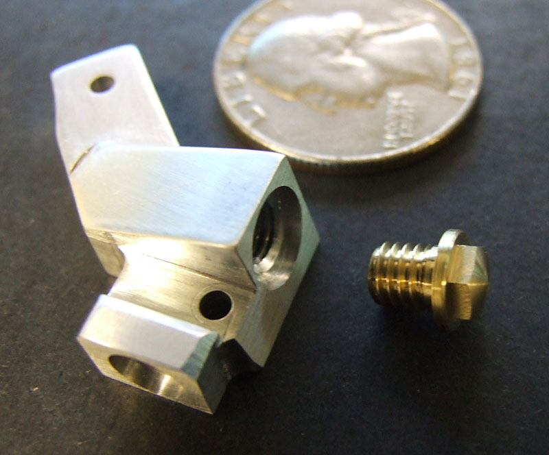
Brass Distributor Housing
The brass distributor housing was completed. (2/8/08)
Brass Distributor Housing
Here the finished housing is shown with the spark advance arm attached with two small screws.
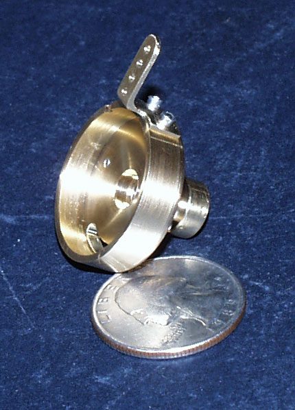
Distributor and Drive Unit
The completed distributor and drive unit were assembled. (2/20/08)
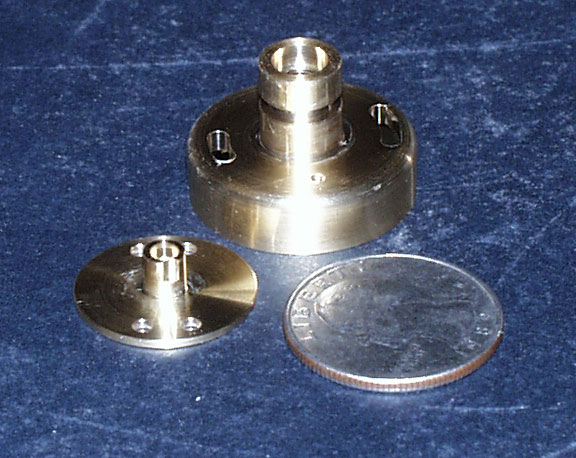
Distributor and Drive Unit
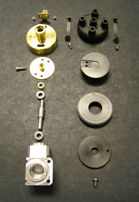
The disassembled component parts of the distributor and drive unit.
Oil Pump Progress
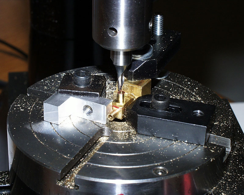
The body of the brass oil pump inlet elbow was milled to 1/8” OD using the rotary table. (2/21/08)
Oil Pump Inlet Elbow
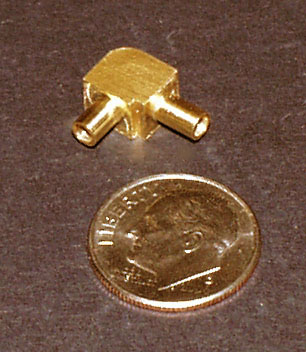
The completed oil pump inlet elbow. Though small, this part required a number of different machining operations.

Oil Pump Inlet Elbow
The finished elbow is smaller than a dime.
Howell V-4 Engine Progress—March/April, 2008
Timing Gears
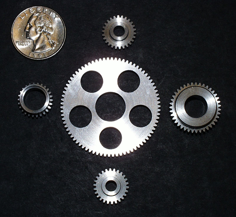
The timing gears were completed by March 10, thanks to some help from Fred Smittle. The gears were made using a Sherline mill and CNC rotary indexer.

Air Cleaner Cover
The air cleaner cover was completed by Dave Eggert of Mission Viejo, CA. He sent us these photos of the finished part.
Air Cleaner Cover
Dave was still working on some of the brass fittings for the cover at this point, but the photos make clear that he did a really nice job on the part.
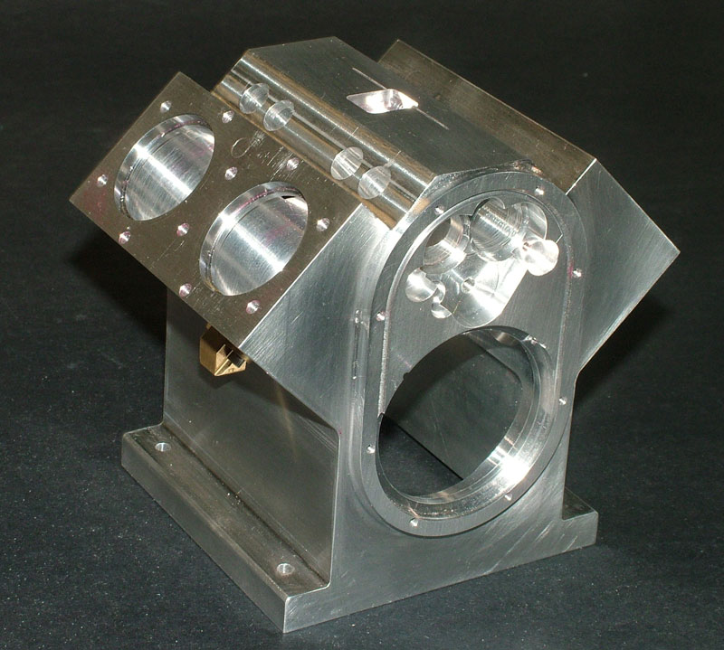
Howell V-4 Engine Block
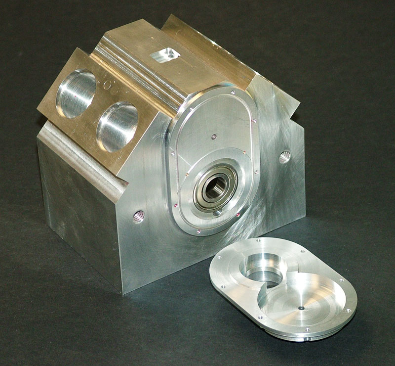
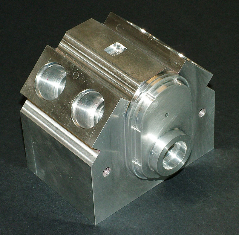
The front face of the engine block was relieved, leaving an oval boss. The front cover exactly matches this shape. The cover also has a raised circular area that fits into a matching countersunk area of the block, in front of the main bearing. (3/20/08)
Howell V-4 Engine Block
This photo shows the cover in place but not bolted on. The machining operations required several different setups on the rotary table to cut the oval shapes.
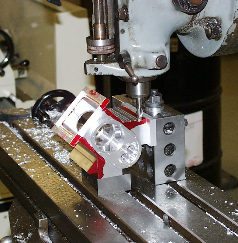
Machining the Engine Block
Tom took this photo while the block was still mounted to the Bridgeport mill table. The sides of the block were being milled away, removing the hold-down fixture holes used earlier. The result was a classic V shape profile. (4/10/08)
Howell V-4 Engine Block
The block was removed from the mill, and the sharp corners were broken slightly with a file. The raw block of 7075 aluminum started out at a weight of 6.32 pounds. At this point, it weighed just 1.42 pounds. Almost 5 pounds of metal had been removed by many machining processes over the course of seven months. With that many hours of work invested in one part, each operation was approached with great care. Tom definitely didn’t want to have to start over now. Consider the photo taken at the beginning of this project of Tom holding the raw aluminum billet—the V-4 engine has come a long way!
Howell V-4 Engine Progress—May/June, 2008
Air Cleaner Cover
Dave Eggert sent in the completed air cleaner cover and mounting components. Although we still had a ways to go before being ready to mount them, it was nice to add these parts to the collection. The finishes are really beautiful, thanks to a great job from Dave. (5/12/08)
Aluminum Rocker Arms
Meanwhile, Tom had been working on the eight aluminum rocker arms, and completed those, too.
Machining Rocker Arms
Tom used this fixture in the rotary table to machine the outer shape of the rocker arms.
Howell V-4 Engine Block
Progress on the block continues.

Various Fixtures
Shown here are some of the many fixtures that Tom had to make to complete several parts and operations.
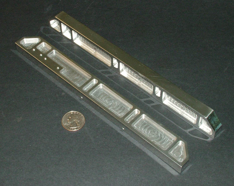
Engine Rails
Adam Krichbaum sent in his CNC machined and polished mounting rails, which the engine and radiator would eventually rest on. (5/16/08)
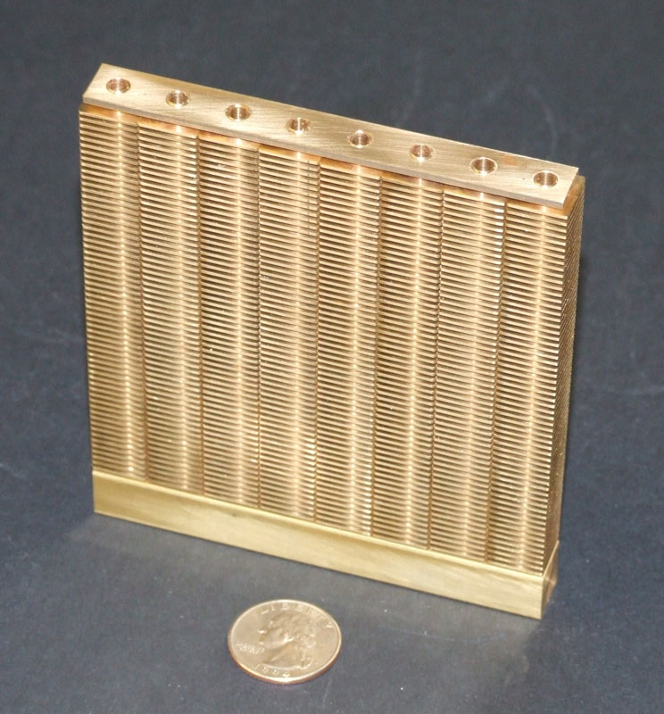
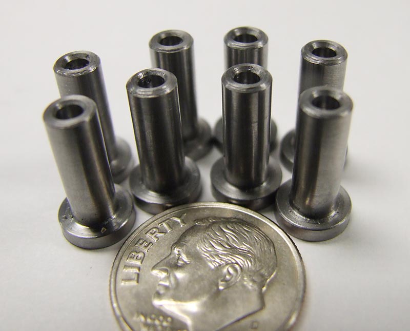
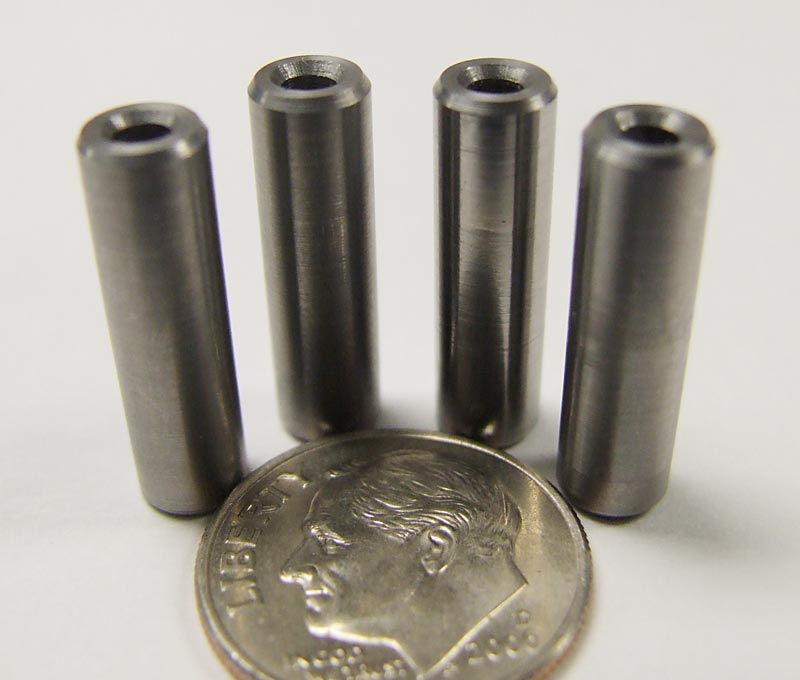
Radiator Progress
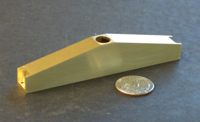
By June 6, 2008, Tom had been working on the radiator for a couple of weeks. The tedious part was making the eight brass, finned rods out of square bar stock. Many grooves were cut using the parting tool, and then a hole was drilled down the middle from each end.
Radiator Progress
A top and bottom tank were then made to connect all eight finned rods. This photo shows the eight finned rods assembled with the bottom tank. Aluminum side pieces were also bolted to the top and bottom tanks to act as a support.
Radiator Top Tank
The top tank of the radiator before installation.
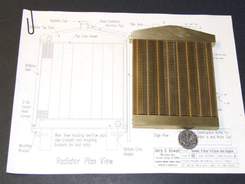
Howell V-4 Radiator
The full radiator assembly placed on a set of plans.
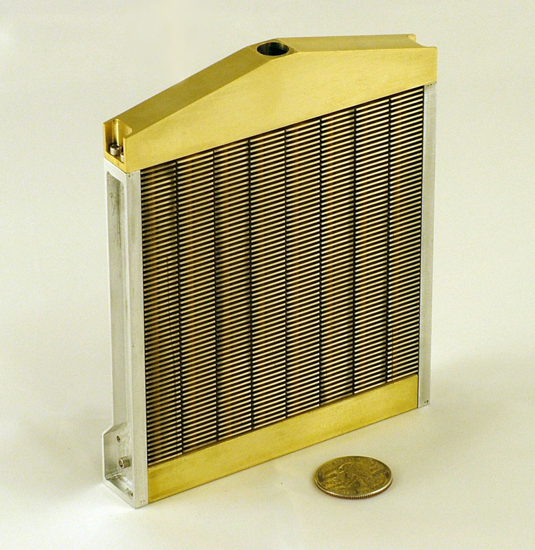
Howell V-4 Radiator
The final radiator assembly includes the aluminum side supports bolted into place. At this point, it was almost ready for soldering to seal it up.
Howell V-4 Progress
The radiator lower mounting brackets were fabricated. With that, the radiator could now be bolted onto the frame rails. (6/13/08)

Howell V-4 Progress
Howell V-4 Engine Progress—July-September, 2008
Machining the Connecting Rods
By July 30, 2008, Tom had completed the connecting rods. They are a split base type rod, because the V-4 arrangement of this engine has the two banks of pistons directly opposite each other—as on a double V-twin motorcycle arrangement.
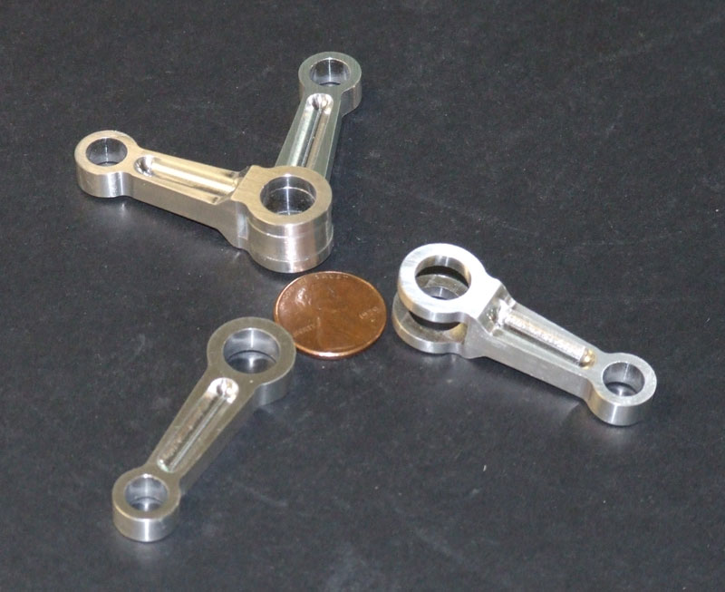
Howell V-4 Connecting Rods
Because the crankshaft is built up inside the case, the bases of the rods do not need to be split and bolted back together. Bronze bushings would be pressed in to provide a wear surface.
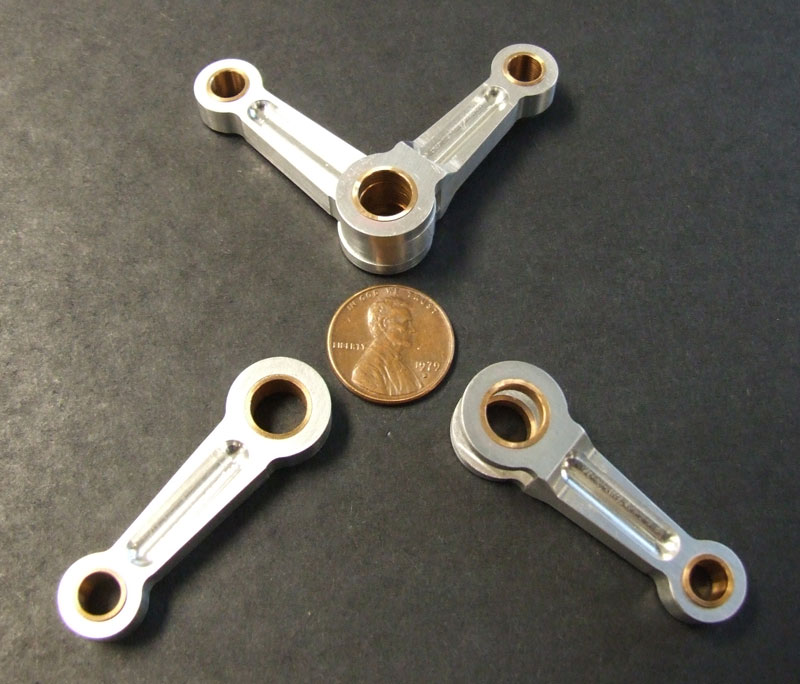
Howell V-4 Connecting Rods
The bronze bushings were turned and pressed into the aluminum connecting rods. (8/28/08)
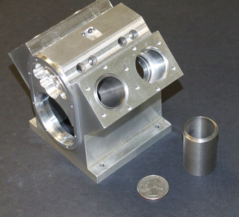
Howell V-4 Engine Block
Also in August, Tom was in the process of turning the four steel piston sleeves, which would be secured in the block using O-rings. The closest cylinder hole has a sleeve in place, while the other sleeve is displayed outside the block. A US quarter provides scale reference.

Howell V-4 Progress
Bronze valve guides were machined for the block and head—eight each, plus a spare. (9/9/08)
Howell V-4 Progress
The plans actually call for the pushrod guides in the block to be square; however, they were easier to make round, and that’s the way they are on Jerry’s prototype. So Tom made them that way, too.
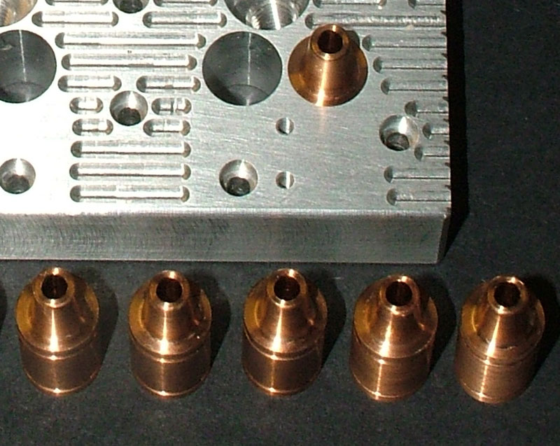
Howell V-4 Engine Progress—October/November, 2008
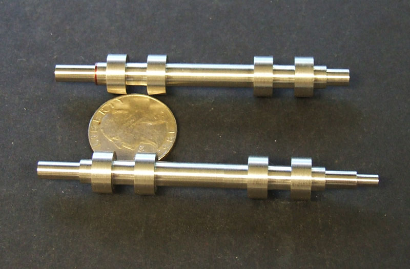
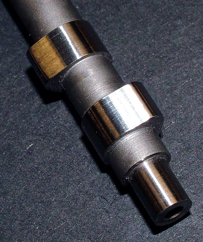
Howell V-4 Crankshaft
The crankshaft parts are disassembled here. The crank elements still needed to be machined to shape and drilled. Then the pins that connect them would be turned to complete the crank.
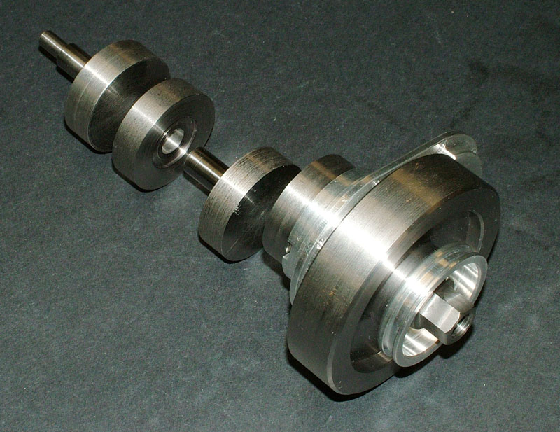
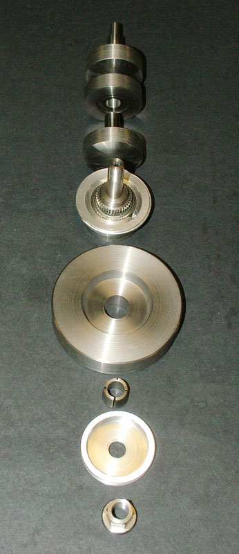
Howell V-4 Crankshaft
The built-up crankshaft is in progress. The flywheel, collet, pulley, and nut are assembled here, with the other three pieces of the crank laid out behind. (10/10/08)
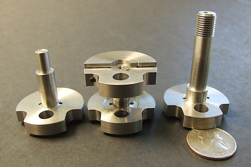
Crankshaft Counterweights
The crankshaft counterweights were fully machined, ready for installation in the engine block. (11/19/08)
Howell V-4 Crankshaft
The crankshaft center bearing holder was installed in the block.

Howell V-4 Crankshaft
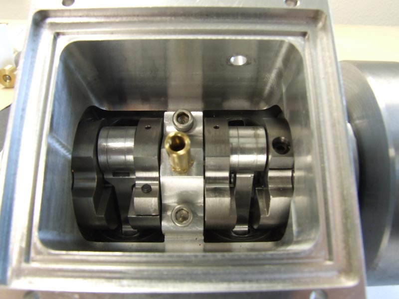
Finally, the crank was installed in the block for testing, and it spun as smooth as butter!
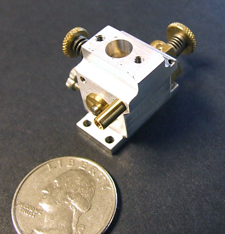
Howell V-4 Carburetor
The finished carburetor with a quarter for scale reference.

Howell V-4 Carburetor
Here the carburetor is shown with the air cleaner made by Dave Eggert installed.
Howell V-4 Engine Progress—January-March, 2009
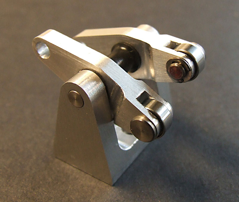
Howell V-4 Rocker Arms
The rocker arms with pins and ball bearings installed. (1/30/09)
Howell V-4 Valves
The valves and valve spring retainers are ready to go.
Howell V-4 Camshafts
Tom and Joe decided to grind the camshafts in a conventional manner, rather than using individually machined, glued on lobes—as the plans called for. This gave Joe another chance to try out the Sherline CNC cam grinder that he developed and used for the Seal engine camshaft. Tom turned an extra set of cam blanks just in case. (3/5/09)

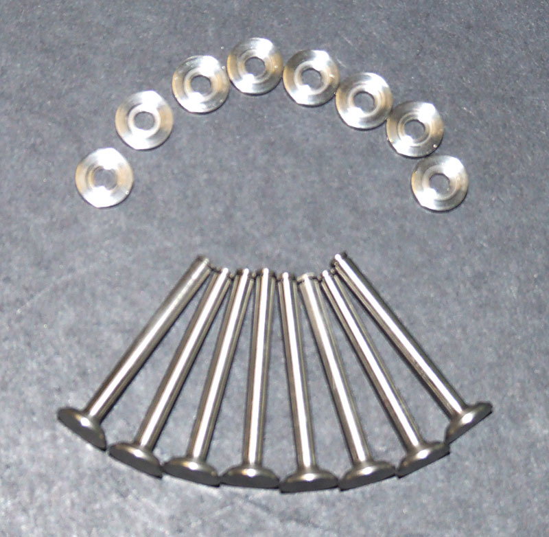
Howell V-4 Pushrod Ends
Eight stainless steel clevises and nuts for the pushrod ends surround a quarter for scale.
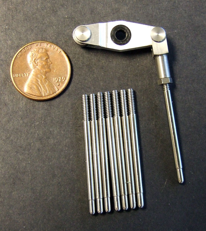
Howell V-4 Pushrods
The pushrods have threaded ends to attach to the clevises.

Howell V-4 Intake Manifold
The intake manifold casting was machined to size, and then bolted in place between the heads. In this photo, the carburetor and air cleaner unit are installed on top, and one of the pushrods is set in place through the bronze guide.
Howell V-4 Engine Progress—April, 2009
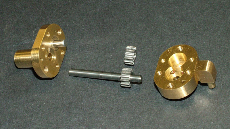
Howell V-4 Oil Pump
Tom finished the components of the oil pump. The gear teeth were cut from cold-rolled gear stock. (4/8/09)

Howell V-4 Oil Pump
The pump halves are assembled with four small socket head screws.
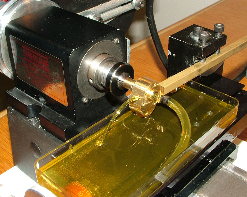
Howell V-4 Oil Pump Test
The oil pump was tested and run-in by powering it with the Sherline lathe for a few hours. The intake hose is in the foreground. Coming from the left side of the pump itself is a stream of oil created by the interlocking pump gears.
Howell V-4 Oil Galley
The aluminum oil galley with its brass plug. (4/24/09)
Howell V-4 Oil Galley and Pump
The galley was installed between the block and oil pump.
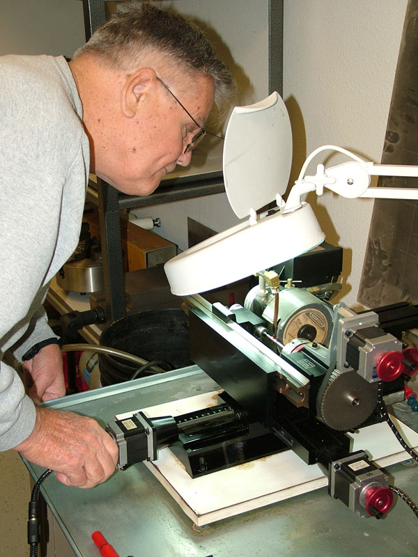
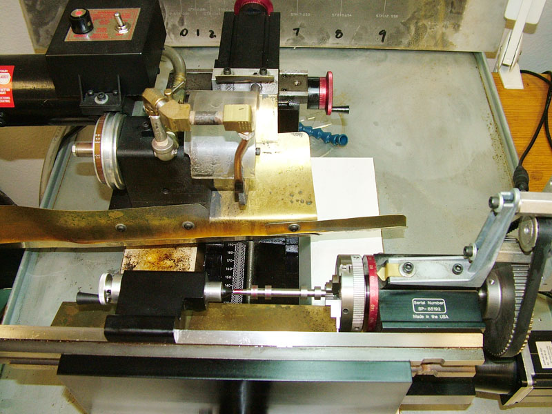
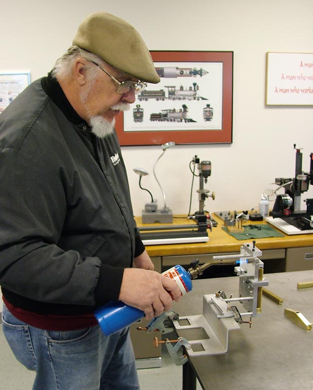
Joe Grinding the Cam
Joe Martin is shown setting up and using the Sherline cam grinder to finish the two overhead camshafts for the Howell V-4.
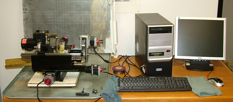
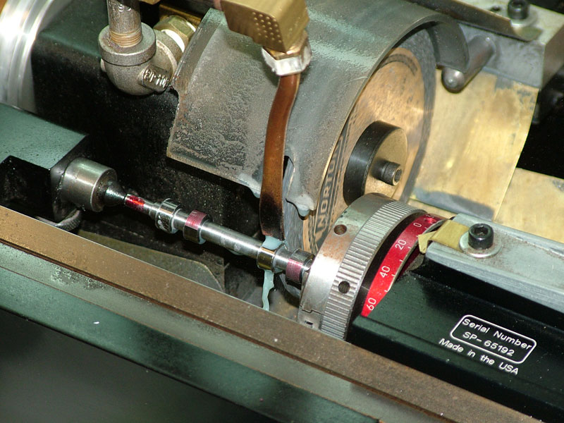
Sherline Cam Grinder
Computer controlled axes move the camshaft back and forth and rotate it while the spinning grinding wheel takes them down to size and shape, one pass at a time.
Sherline Cam Grinder
Jerry’s plans call for individual cam lobes to be pinned and glued onto the camshaft blank, but we decided to grind them in one piece.
Sherline Cam Grinder
The next step was to case harden the camshafts, which Tom would do in the museum shop.
Howell V-4 Camshafts
The first time around, a mistake was made in the orientation of the cams on the shaft. When redoing them, we decided to Harden the blanks first, and then grind the cam lobes after hardening. This provided a better finish on the cams. The second set of camshafts were turned from A2 tool steel, and hardened to 60 Rockwell. The hardening process for the first set is detailed further down this page.
Joe Martin’s cam grinder worked so well that they decided to add the machine to the Sherline catalog. Below you can watch two videos of the cam being ground for this project.
Howell V-4 Engine Progress—May, 2009
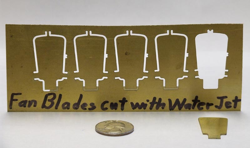
Howell V-4 Fan Blades
Pam Weiss programmed the fan blade profile into Sherline’s Flow waterjet cutter. She then cut five blades from a sheet of brass, leaving only a few small tabs to retain the fans in the sheet. (5/22/09)
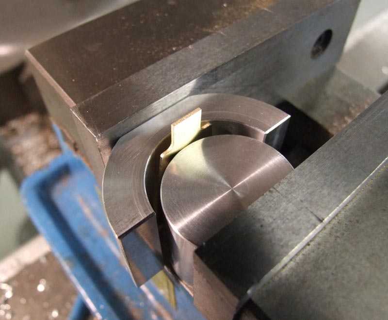
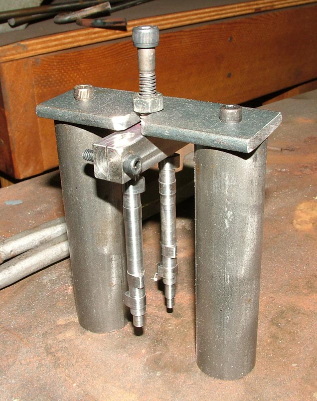
Curving the Fan Blades
Tom then cut the tabs and filed the blades to shape. After which, he used the fixture in this photo to put the required foil curve into each blade. Here, the vise has not yet closed on a straight blade.
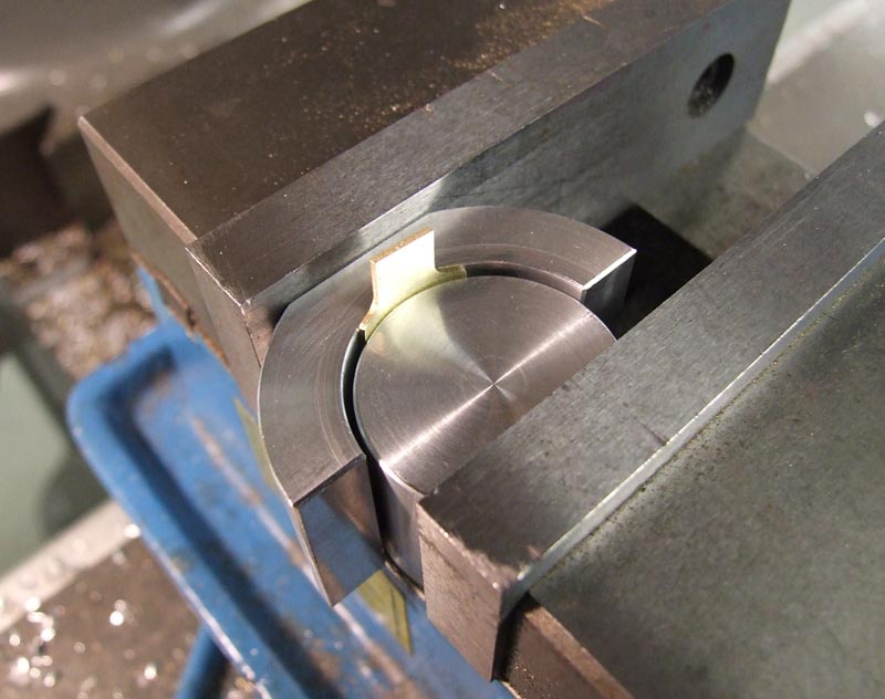
Curving the Fan Blades
The blade is now curved after tightening the vise.
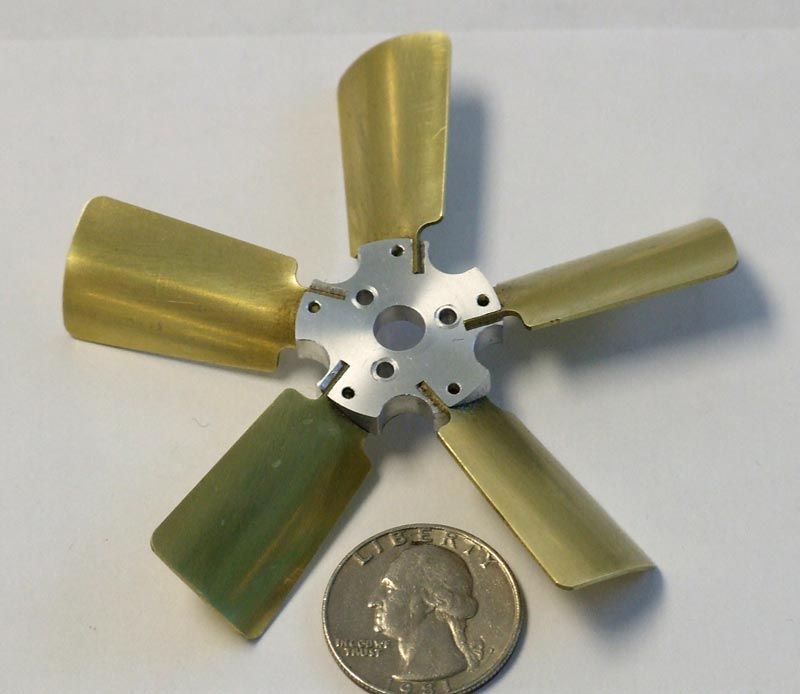
Howell V-4 Fan
The blades were glued and pinned into slots on the fan hub.
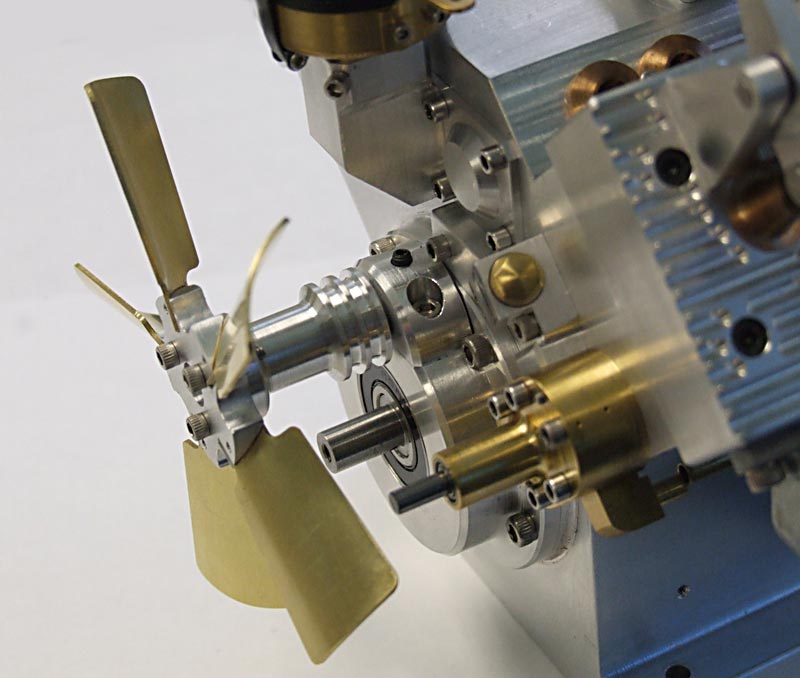
Howell V-4 Fan
The fan was set into place on the engine, along with the pulleys.

Howell V-4 Fan Pulley
The fan pulley on its shaft before the fan was attached.

Howell V-4 Crankshaft Pulley
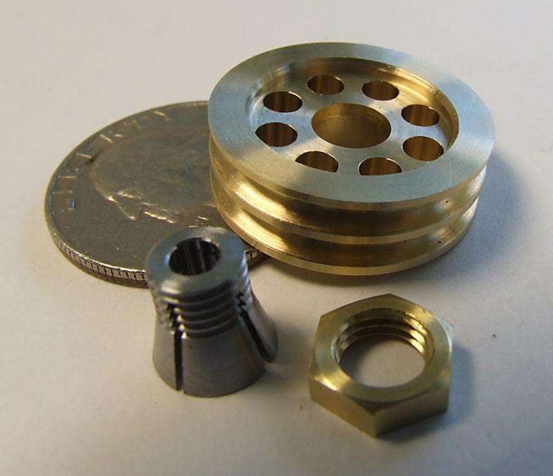
Oil Pump Components
The oil pump pulley, collet, and nut. (5/16/09)
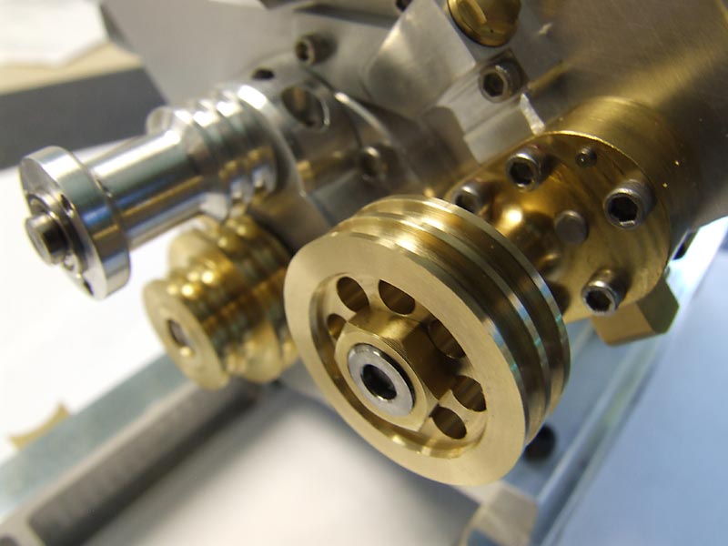
Oil Pump Components
The oil pump components are installed alongside the other pulleys.

V-4 Fixtures and Tools
Larry Simon worked on some of the tooling for the engine. Pictured from the very top moving clockwise are a piston installing tool, cam setting tool, flywheel puller, cam positioning sleeve, cam gear setting tool, and piston ring thinning holder.
Howell V-4 Engine Progress—June/July, 2009
Howell V-4 Valve Guides
Tom turned the eight valve guides. (6/17/09)
Howell V-4 Wrist Pins
Tom also turned these four wrist pins.
Howell V-4 Progress
The cylinder liners were installed. Then the connecting rods were installed on the crankshaft, and connected to the pistons to make sure everything was in alignment.
Howell V-4 Progress
There were no rings on the pistons yet, so it turned over easily. Either way, it gave Tom some relief knowing that everything lined up and worked smoothly when the crankshaft rotated.
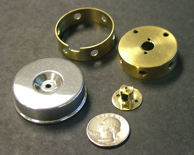
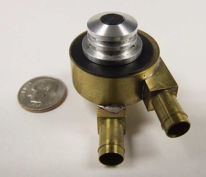
Water Pump Components
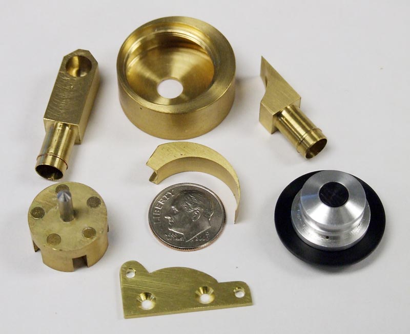
The water pump components are laid out. From top center moving clockwise, the parts include: main housing; water outlet; cover and pulley assembly (consisting of pulley, five rare earth magnets, two ball bearings, and black plastic cover); mounting bracket (bottom); impeller assembly (consisting of impeller, shaft, and five rare earth magnets); water inlet; and in the center above the dime is the cutwater. (7/2/09)
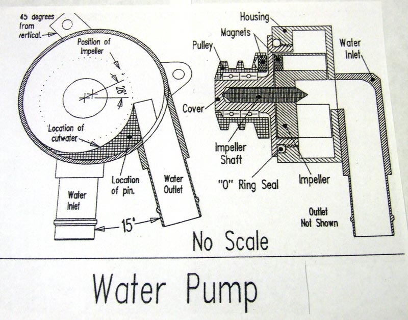
Water Pump Drawing
Jerry Howell’s water pump drawing. The magnets in the pulley drive the impeller by magnetic attraction, thereby eliminating the need for a shaft seal.
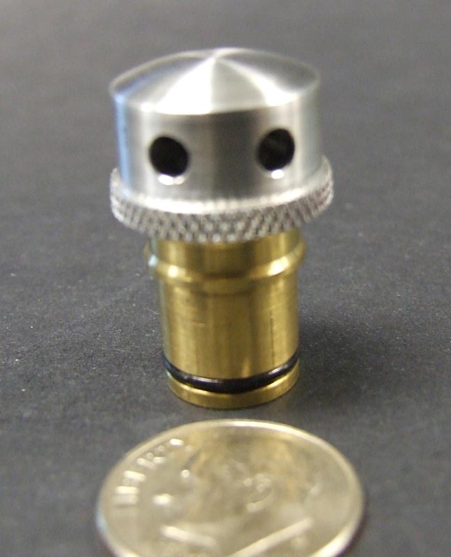
Howell V-4 PCV Valve
The assembled Positive Crankcase Ventilation (PCV) valve with O-ring in place.
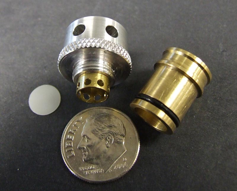
Howell V-4 PCV Valve
The individual parts making up the PCV valve. From left to right are: the check valve disk; the breather top with brass valve and disk travel limiter installed; and the breather bottom and check valve body assembly.
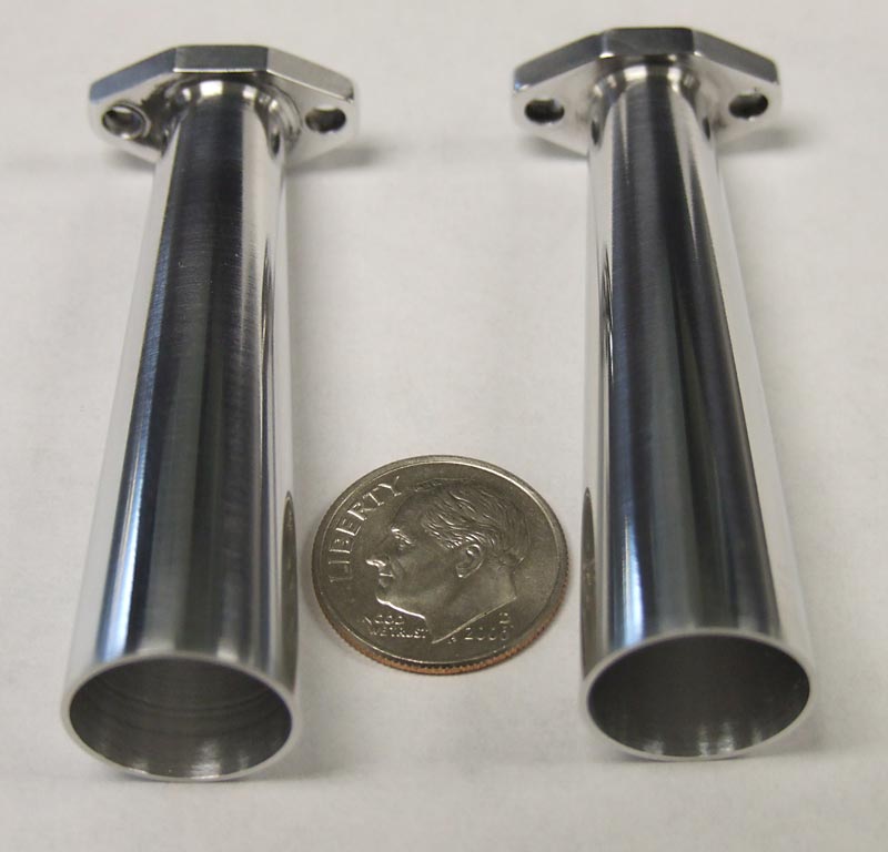
Howell V-4 Exhaust Tips
Tom’s highly polished, tapered megaphone exhaust tips depart from Jerry’s prototype. These give a racier character to the somewhat industrial looking engine.

Howell V-4 Progress
Tom had also installed a similar exhaust tip on the Seal engine, and we liked the way it sounded.
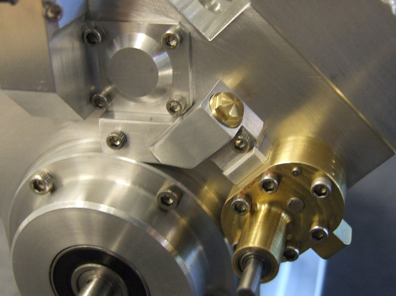
Howell V-4 Water Pump
The water pump was soldered and assembled. (7/23/09)
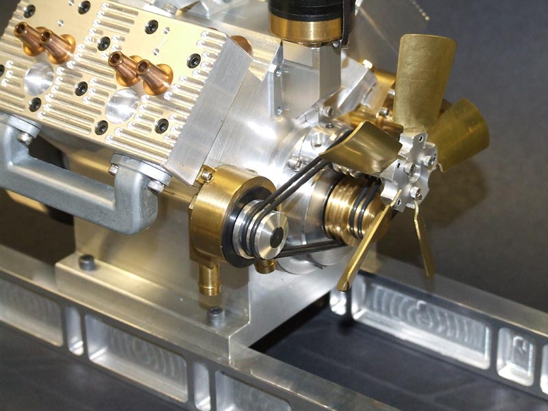
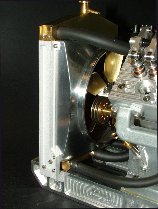
Howell V-4 Front End
The water pump was temporarily installed on the engine, along with the fan.
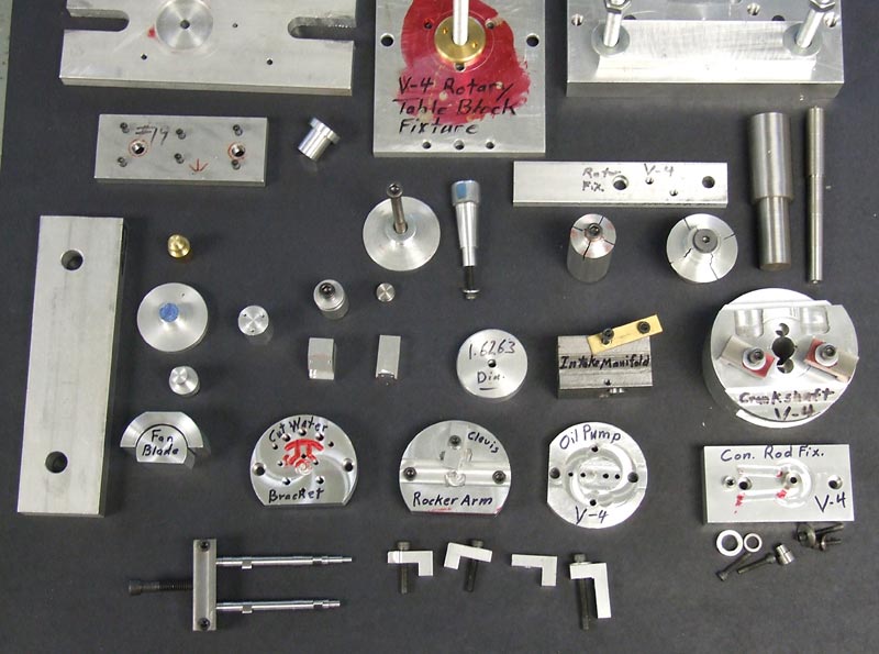
Howell V-4 Fixtures
Some of the many fixtures that Tom built in order to make parts for the engine.
Howell V-4 Engine Progress—August/September, 2009
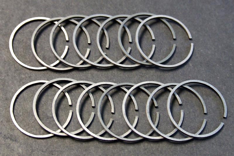
Howell V-4 Piston Rings
The original plan was to buy finished piston rings, and grind them to proper thickness. It was eventually decided that they should actually be made in-house. Tom turned these piston rings from cast iron, and heat treated then using Sherline’s heat treating oven. The usual practice is to make about twice as many as needed, as they can break. These 15 rings would need to be enough once final assembly began. The rings are .875” in diameter, and .040” thick. (8/20/09)
Heat Treating the Camshafts
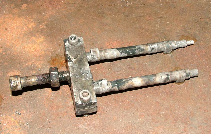
The following photos were taken when we heat treated the first pair of camshafts. (A subsequent pair was heat treated prior to grinding the lobes.) Here the cams are clamped in their holding fixture, ready for heating. (9/4/09)

Heat Treating the Camshafts
Tom inserts the fixture into the heat treating oven.
Heat Treating the Camshafts
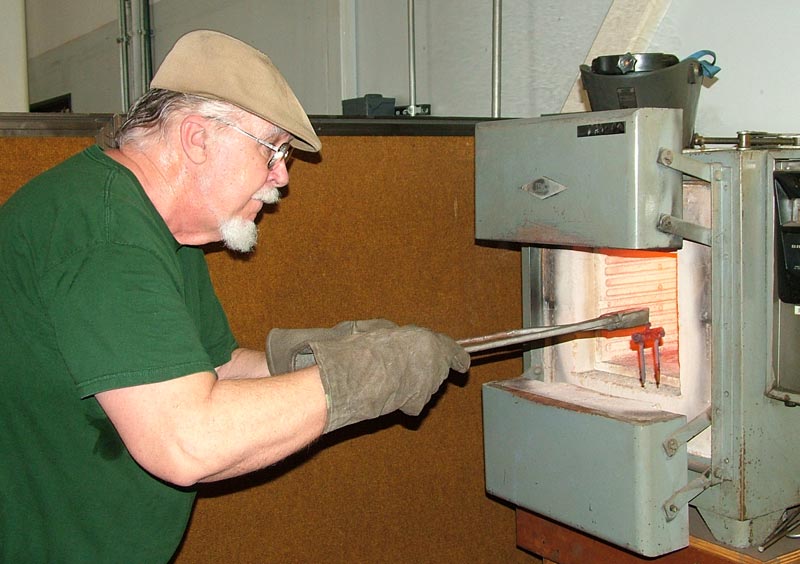
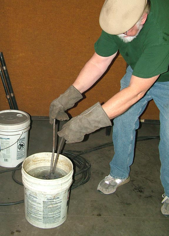
The heated fixture, with the cams glowing bright red, is brought out of the oven. Notice this time that Tom is wearing welding gloves. It is incredibly hot next to the open oven door.
Heat Treating the Camshafts
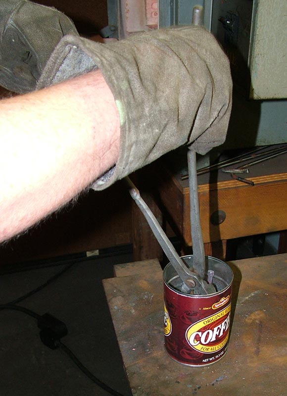
The cams are plunged directly into the Kasenit heat treating powder, and allowed to sit until a coating melts to the surface.
Heat Treating the Camshafts
The still glowing fixture soaks in the Kasenit powder.
Heat Treating the Camshafts
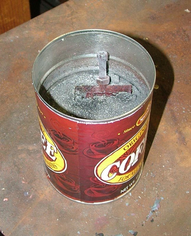
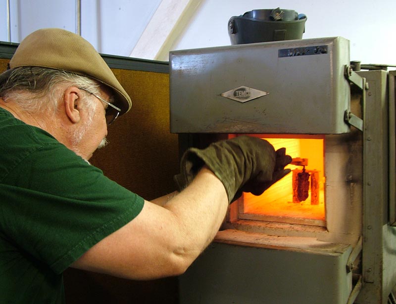
After scraping off most of the clumped powder clinging to the cams, the fixture is returned to the oven once again. The excess powder is burned off.
Heat Treating the Camshafts
Tom removed the red hot fixture from the oven for a final time, and plunged it into the water tank to cool. The cams must be lowered in straight, so that one side doesn’t cool faster than the other. This keeps the cams from warping. Surprisingly little steam was created in the process.
Heat Treating the Camshafts
The finished heat treated cams ready to be removed from the fixture. They needed quite a bit of cleanup. Unfortunately, after all that work had been done, it was determined that a G-code error in the cam program caused the lobes to be positioned incorrectly. Because of this, a second pair had to be made.
Howell V-4 Engine Progress—November/December, 2009
The second time around, we tried a different approach with the cams. Instead of case hardening the surface, blanks were turned from A2 air-hardening steel, and wrapped in stainless steel foil. They were then brought to 1745° in the heat treating oven. A small piece of paper was placed inside the foil with each blank. The paper would burn up and remove any oxygen trapped inside the foil.
Howell V-4 Cam Blanks
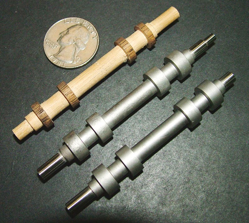
The second set of cams is shown here, hardened and ready for grinding. The ends have already been centerless ground to size in Sherline’s grind shop. A wooden blank was turned from a dowel, and was used with a 4″ saw blade instead of the grinding wheel to test the cam program. We wanted to make sure it was correct this time before grinding the steel blanks. (11/6/09)
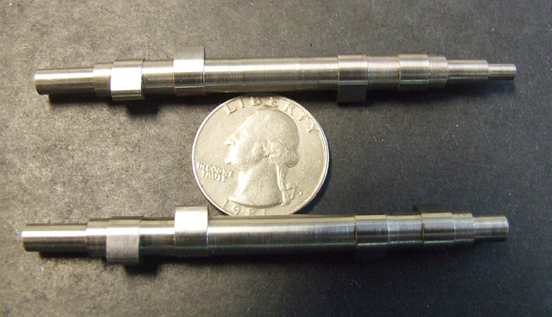
Howell V-4 Camshafts
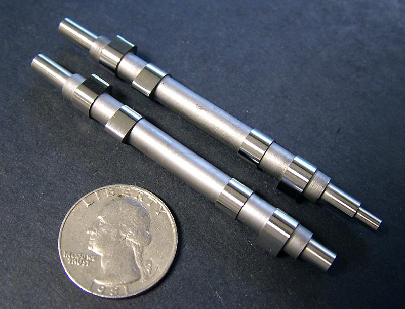
The finished camshaft pair. After finding the simple G-code error, Joe made some changes, and ground the first blank on the Sherline CNC cam grinder. It came out perfectly this time. Tom finished up the second cam, which was a relatively quick process now that the code was dialed in. The cam gears were pressed the next day. (11/11/09)
Howell V-4 Camshaft
Getting the cams ground was the last big hurdle before final assembly. We were getting very close at this point.

Howell V-4 Progress
On December 16, 2009, preliminary assembly of the whole engine was done to test-fit all the parts. The piston rings and cams were installed, and everything turned smoothly. The next project was to solder the radiator parts together. It took over two years to get to this point, but the “first pop” was in sight now!
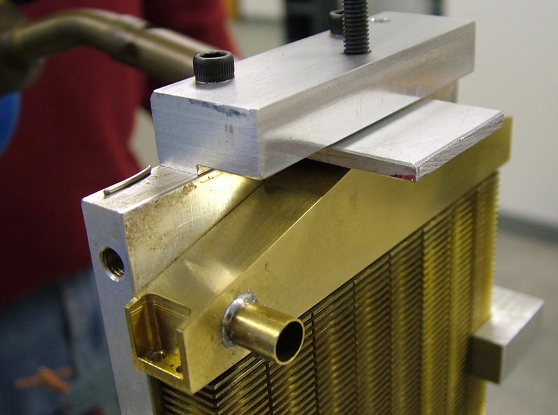
Tom Soldering the Radiator
The eight brass bars making up the radiator are mounted to an aluminum plate, and paste solder is applied to the joints on the top plate and bottom tank. Heat is applied to back of the aluminum plate with a propane torch. (12/30/09)
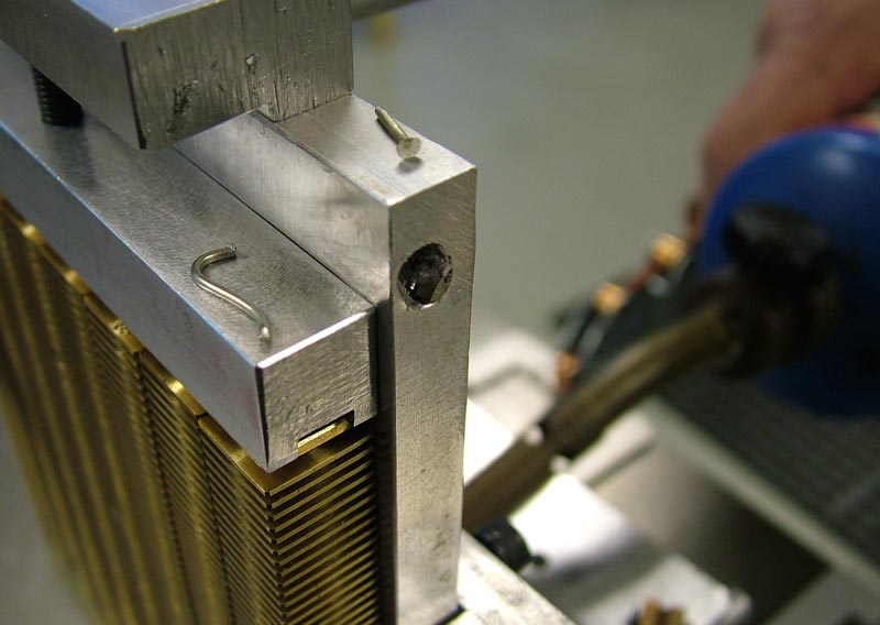
Soldering the Radiator
Tom placed small strips of solder on top of the fixture at two points on each side.
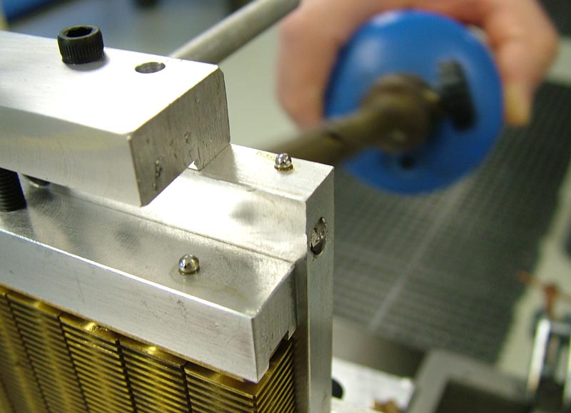
Soldering the Radiator
Per Jerry’s suggestion, when the solder melts into a ball (shown here), the solder on the joints of the radiator is also melted. At that time the heat can be removed. Once again, Jerry’s suggestion worked great!
Soldering the Radiator
The top tank is placed in the fixture, and paste solder is applied to the joint. The fixture is again heated with a propane torch. (12/31/09)
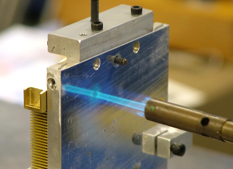
Soldering the Radiator
In these photos, the sample piece of solder had not yet melted. This part went faster, as only the top part of the plate had to be brought up to temperature.
Howell V-4 Engine Progress—January-March, 2010

Howell V-4 Radiator
The completed radiator was tested with air pressure while submerged underwater. A small initial leak around the bottom hose fitting was found, and that joint was re-soldered. The radiator now held pressure, and the side plates were ready to be attached. (1/5/10)
Howell V-4 Radiator
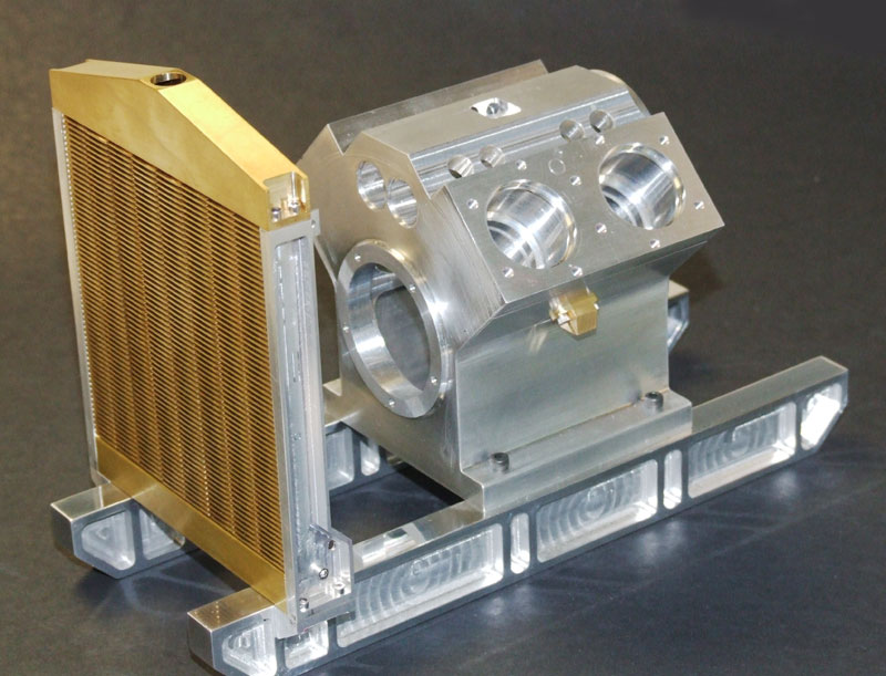
The radiator is installed on the rails in front of the engine.
Howell V-4 Engine
An overall shot of the engine and radiator in the preliminary assembly stage. Once all fits were checked, the engine would be disassembled again. Some parts were bead blasted, and others painted, so that the engine could be reassembled for the final time.
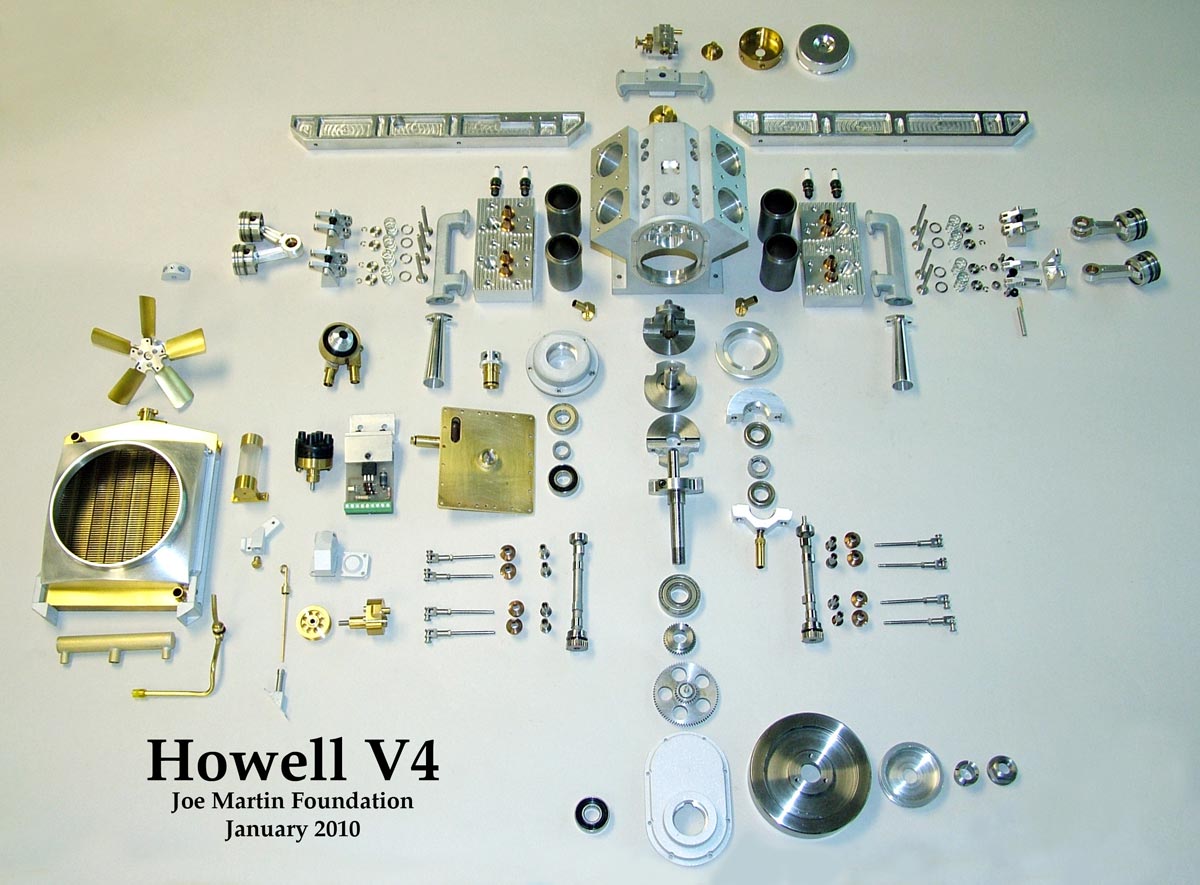
Disassembled Howell V-4 Engine
All of the parts for the Howell V-4 are laid out here prior to final assembly. There are actually more individual parts than can be seen here, because the carburetor, distributor, radiator, oil and water pumps, and other assemblies were not fully taken apart. The block and some of the other parts were bead blasted to give a cast appearance. The rest were left with a natural or polished finish. The final step was to turn this array of parts into a completed engine at last. (1/21/10)
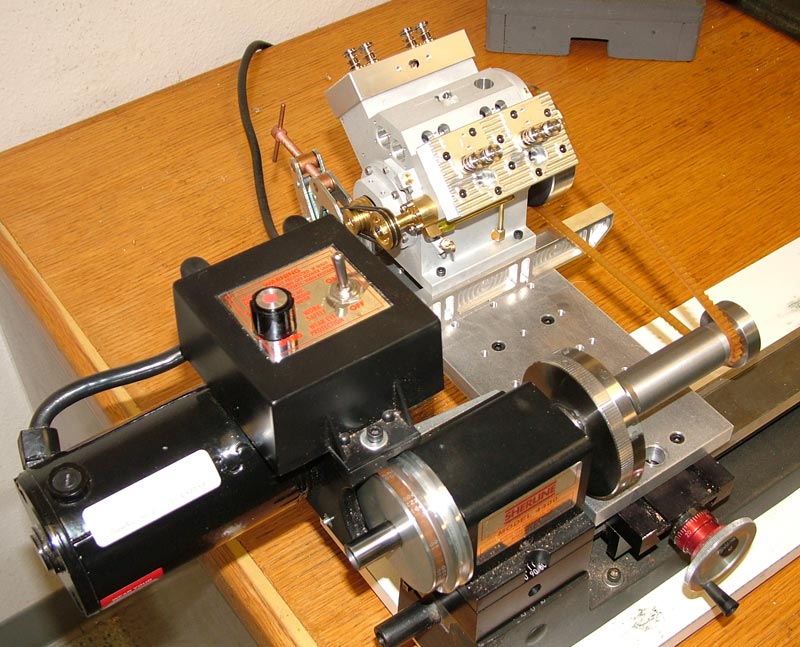
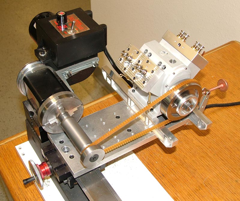
V4runin1
Tom installed the heads, crank, pistons, and rods. Then he hooked the flywheel up to a pulley on the Sherline lathe, and let the engine run for a few hours to seat the piston rings. (2/3/10)
Howell V-4 Run-In
Howell V-4 First Firing
The engine and radiator were reassembled, and then mounted on a temporary “breadboard” to connect the electrical components for a first firing. Tom was checking all the electrical connections to see why the timing light wasn’t turning on. He wondered if it could be a bad Hall sensor. (3/11/10)
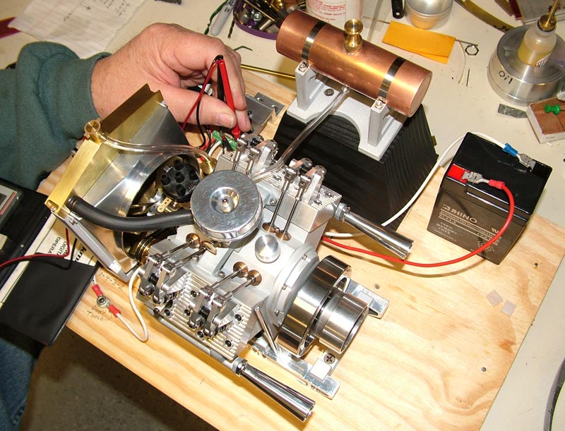
Howell V-4 First Firing
Tom was also working on constructing a throttle linkage. We were very close now. Once the engine was running, Craig would make the final oak display base. All of the electrical components would be mounted out of sight underneath the base.
Success! Howell V-4 First Pop—March 16, 2010
On March 16, 2010, we successfully completed our second Joe Martin Foundation shop project—the Howell V-4 IC engine. Watch a video below documenting the first pop of the engine, along with the first extended run on March 17.
Congratulations to Tom Boyer and all those who helped for a fine job! The engine was put on display in the Craftsmanship Museum for some time following completion. Tom was happy to start it up for any visitor who wanted to see and hear the V-4 in action. The only remaining tasks were to make a throttle and advance linkage, and to build an attractive display base.

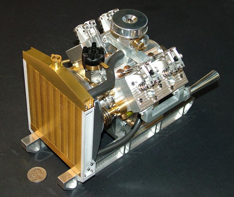
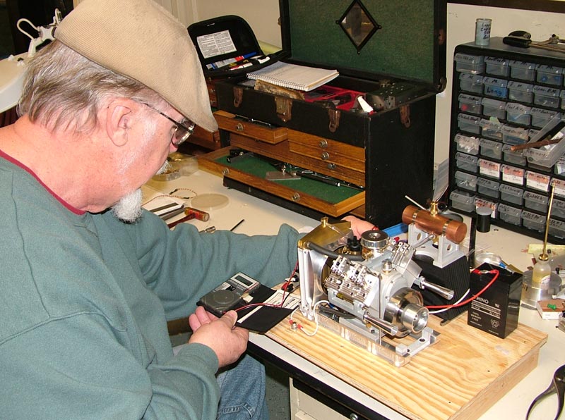
Tom Boyer fine tuning the Howell V-4 engine during its very first run.

A side profile of the finished Howell V-4 engine. All in all, the second museum shop project was a total success.
A Note From Jerry Howell’s Family

In Memory of Jerry Howell
January 8, 1938—August 29, 2009
On behalf of me and my family, we would like to congratulate you and your team on the successful build and run of the Howell V-4. I know Dad was honored to be inducted into your list of craftsmen, and again when you chose to build his V-4.
Dad cannot express his gratitude personally, but again on behalf of my mother Edith, sister Sherry, brother Roger, and myself, we would like to say a big “Thank You” to the Craftsmanship Museum for all you have done to share and promote his work and his legacy.
Sincerely,
Allen Howell & Family
Howell Engines Made by Other Model Engineers
Dave Sage’s Howell V-8 Project
Jerry Howell’s original design began as a kind of double V-twin to make a V-4. Dave Sage took it to a new level by doubling up on Jerry’s design to make the engine into a V-8. Naturally, he had to make his own modifications in order to support the longer built-up crankshaft. He also modified the camshafts to change the timing and firing order, making it more like a Chevy small-block V-8. When asked why, Dave responded, “just for the heck of it.” In these early photos taken soon after the first run, Dave’s V-8 is running a single carburetor.
Dave said that engine speed was limited at this point, and to get more rpm out of it he would probably have to add more carbs. Our only regret is that while Jerry Howell saw the start of this project, he didn’t get to see the ambitious extension of his original design finished and running. It looks like Dave did a first class job that Jerry would have approved of.

Dave Sage’s Howell V-8 Engine
(Photos courtesy of Dave Sage.)

Dave Sage’s Howell V-8 Engine
(Photos courtesy of Dave Sage.)
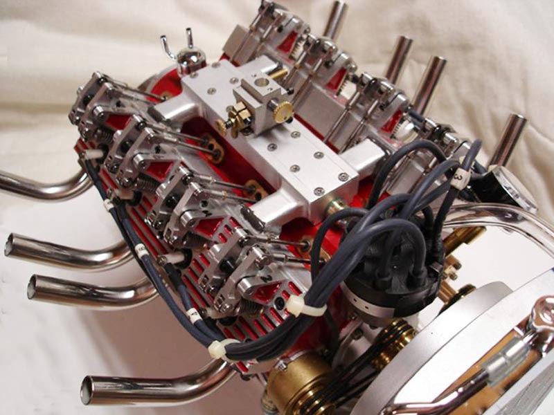
Dave Sage’s Howell V-8 Engine
(Photos courtesy of Dave Sage.)
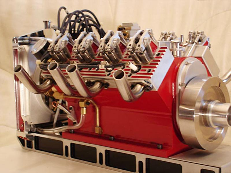
Dave Sage’s Howell V-8 Engine
(Photos courtesy of Dave Sage.)
Terry Mayhugh’s Howell V-4 Project

Terry Mayhugh’s Howell V-4 engine. (Photo courtesy of Terry Mayhugh.)
Terry Mayhugh started this project—only his second IC engine—shortly after the Craftsmanship Museum started our version. Terry’s first IC engine build was a Howell V-twin. It took Terry about 3,000 hours over the course of two years to complete this engine, but he did a fantastic job. Not only does it look good, but the V-4 runs great, too. Castings for the manifolds were unavailable, so Terry machined his from the plans. Notice also the effective base and innovative gas tank.
Watch a video of Terry’s early run of his Howell V-4 engine.