Below are a number of photos of Ross’ extensive engine building. Click images to enlarge. Captions courtesy of Ross Bishop.
Building the 5148
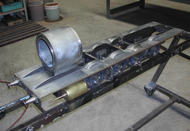
Early Building on the 5148
It’s a sobering time to put all that you’ve made together and see just how little you’ve achieved!
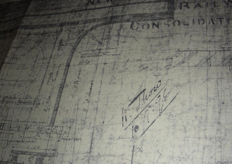
Original Drawing for the 5148
The drawing bears the mark of Chief Mechanical Engineer, W. Thow, dated September 10th 1896.
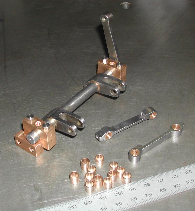
Parts for the 5148
Weighshaft, bronze bushes, and links for the Allen valve motion located between the frames.
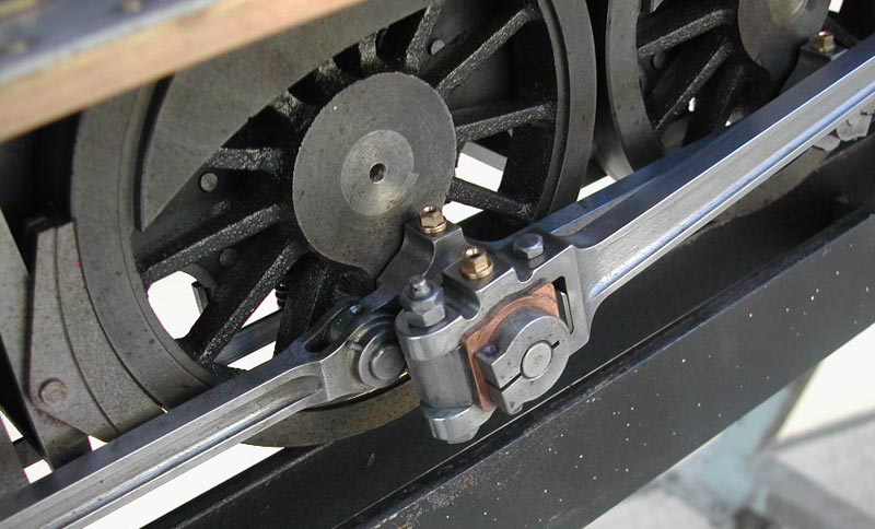
Side rods on the 5148
Side rods need careful milling to achieve proper shape, no undercut radii, and accurate hole centers.
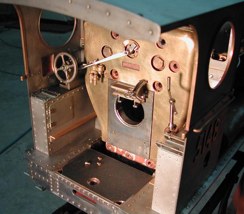
Early Construction of the Cab
Controls match the original.
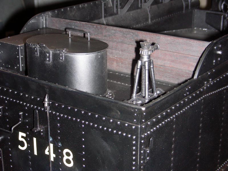
Jack on the Tender
The Jack is shown in position on the rear deck of the tender.
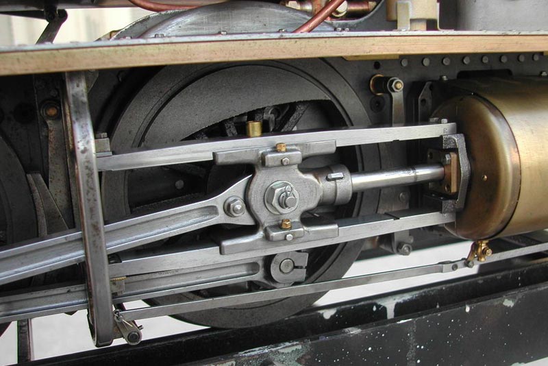
Crossheads for the 5148
The crossheads are a classic feature. These were machined and hand finished from a round cast iron bar. The connecting rod joins with a spherical bearing to accommodate spring movement at the axle end. The full power of the steam is transmitted through the crossheads in spite of them being only 1/16″ (1.5 mm) thick in places.
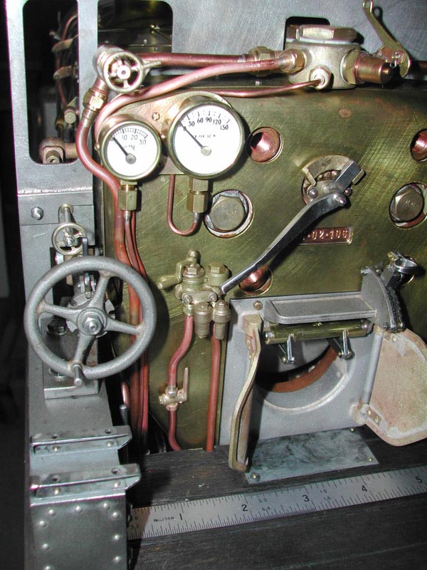
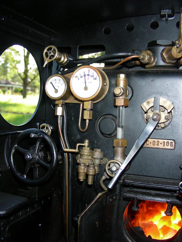
Inside the Cab of the 5148
Left to Right- Screw Reverser (with left hand, double start, square thread, and nut); Air Brake control (working with steam); and Throttle Lever. Gauges show brake function and boiler pressure. A steel rule lying on the “dirtied” floor boards shows size.
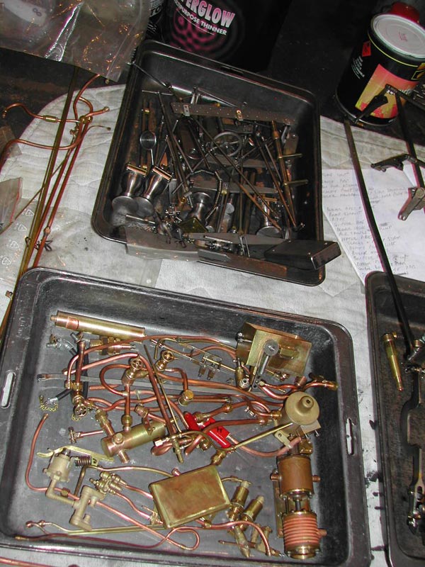
Various Parts
Little by little, the parts accumulate. Some were even made a couple of years before. It’s like seeing an old friend again!
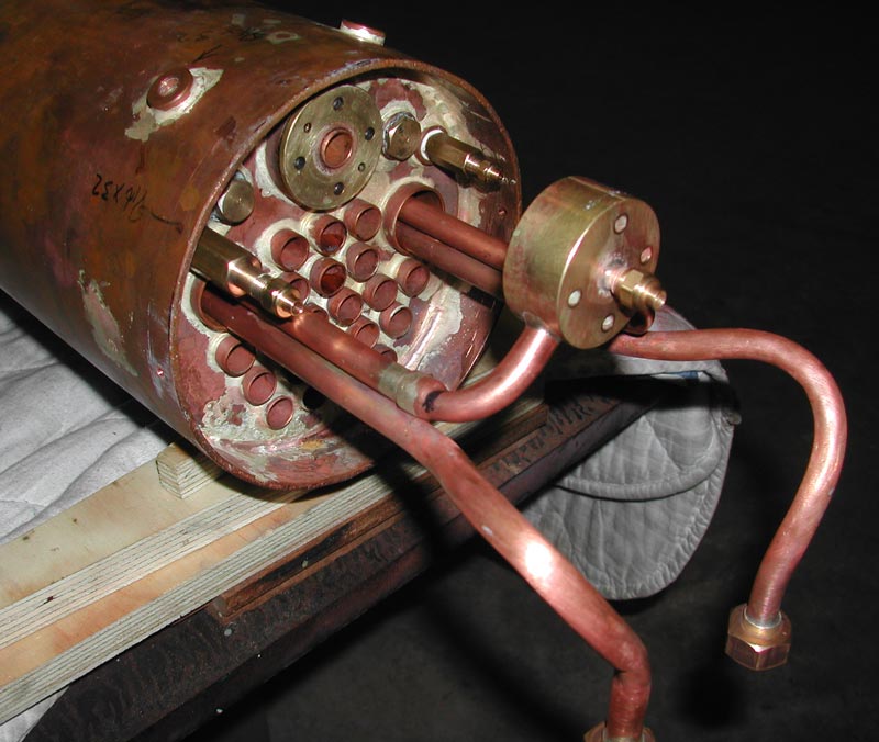
Copper Boiler
The copper boiler (with superheaters) is built to a code, tested and certified. It’s well hidden under the detailed exterior.
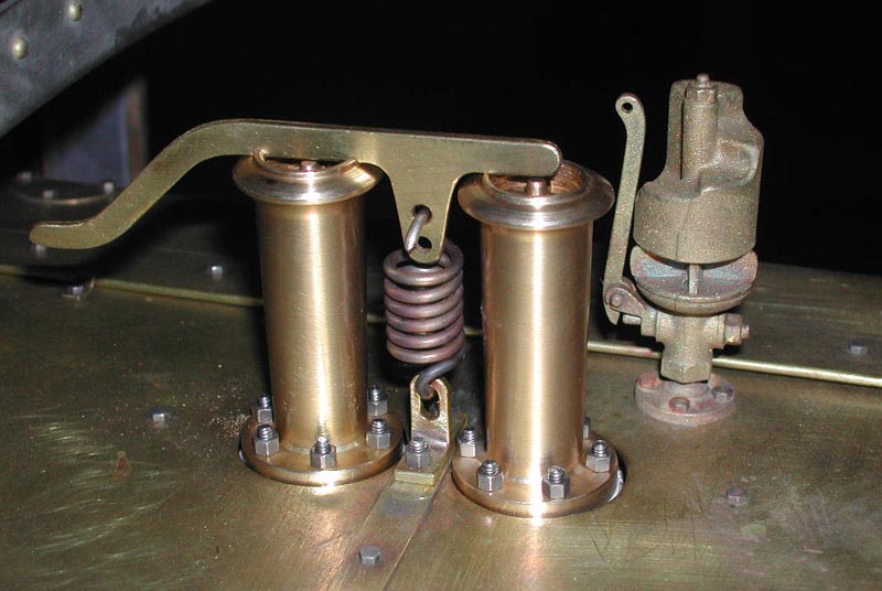
Relief Valves
Approved relief valves on the boiler. The “Ramsbottom” style has been created by adding the lever, spring and 8BA studs as detail only.
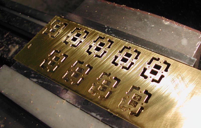
Axlebox Covers
Axlebox covers for the tender bogies. These were milled out manually with great concentration. There’s one extra just in case!
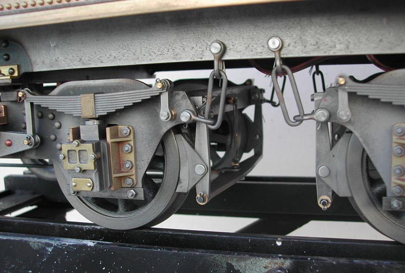
Tender Bogies
Tender bogies with all the links and shackles, brake gear, etc. Used to keep the Blacksmiths busy!
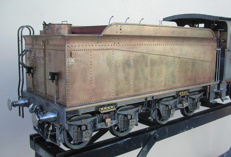
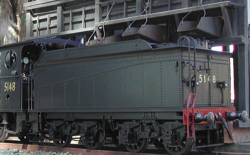
Tender on the 5148
These tenders were used on other local engines too. They are a favorite, and seeing them finished brought great satisfaction.
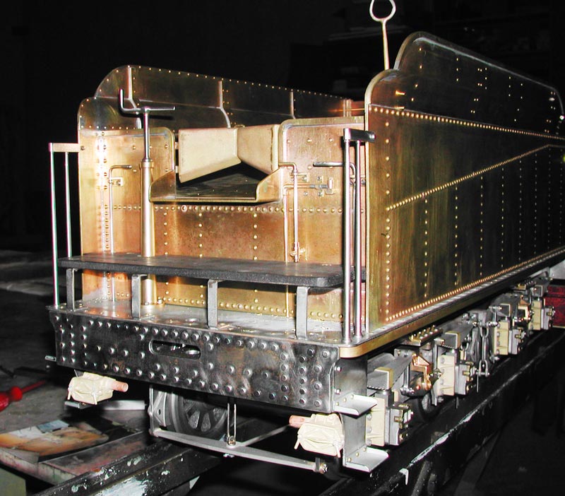
Shoveling End of the Tender
Coal and water for the model is carried within, as well as the driver’s feet on removable pegs.
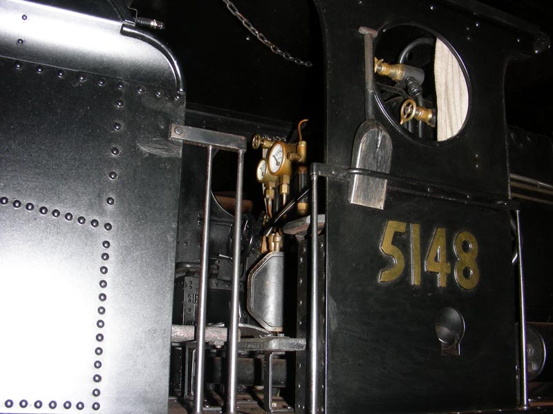
Lineside View of Cab
This might be your view standing lineside. It was a practice of convenience to thrust the coal shovel in the railing when not in use.
Inside the Cab
Once on the footplate and underway this would be the view of the driver’s side.
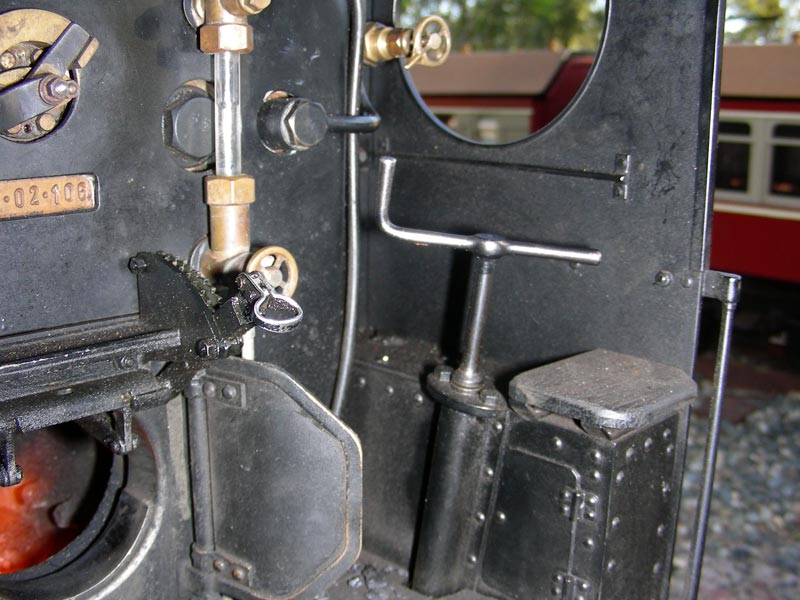
Fireman’s Seat
The fireman’s seat and the “too-high brake handle”.
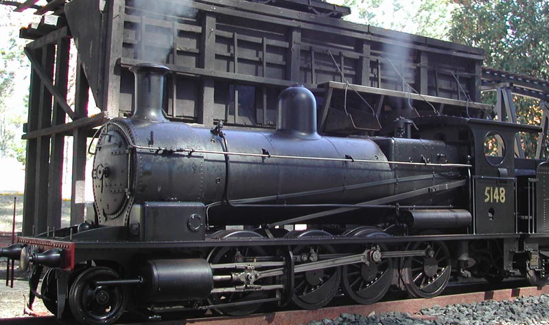
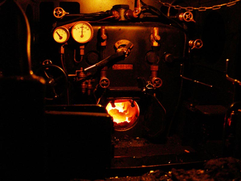
Finished 5148 Engine
A fire breathes life into the machine as a familiar scene from long ago is recreated in miniature.
Finished 5148
Somebody modeled the coal stage at Port Waratah, and this scene is synonymous with the final days of the Standard Goods locomotives.
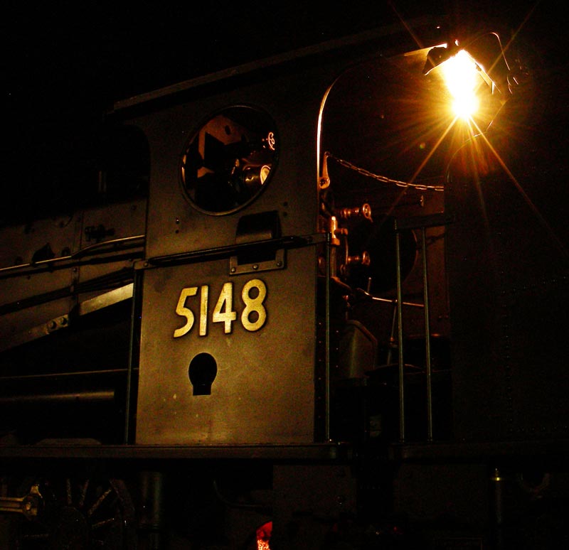
Nighttime View of the Cab
Another world of sensation opens at night, which is illustrated here.
Outside the Cab
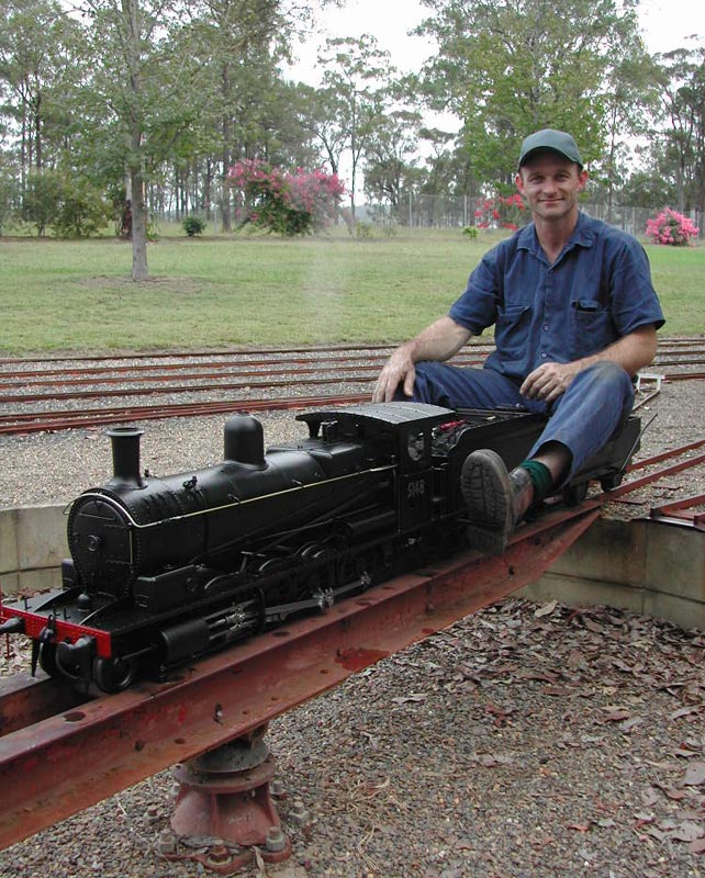
Ross Riding His 5148
Enjoying the unhurried plod of a Standard Goods engine, with a rake of typical wagons from the era. A great escape from the pressures of today’s world.
Building the McLaren Traction Engine
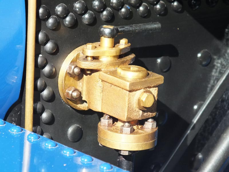
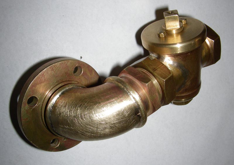
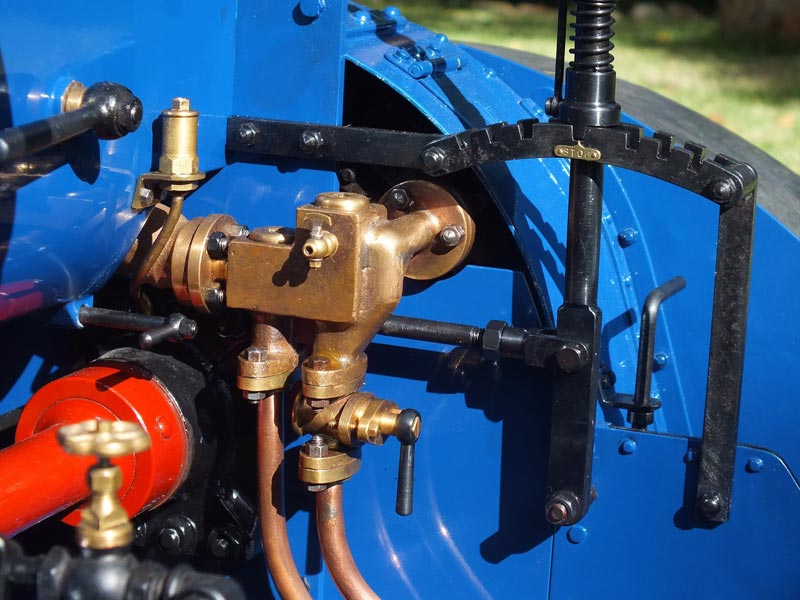
Valve Close-Up
Working in a larger scale such as this permits great attention to detail.
Pipe Fitting Close-Up
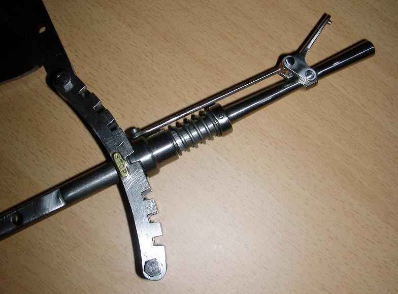
Traction Engine Lever
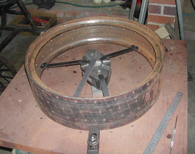
Fitting Spokes
Early fitting of spokes to a rear wheel.
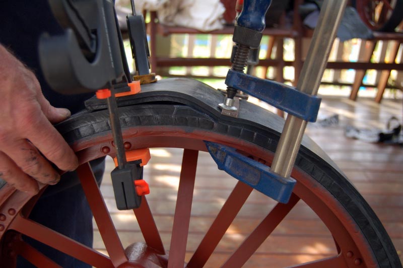
Building Tires
Bonding rubber sheet for the tires.
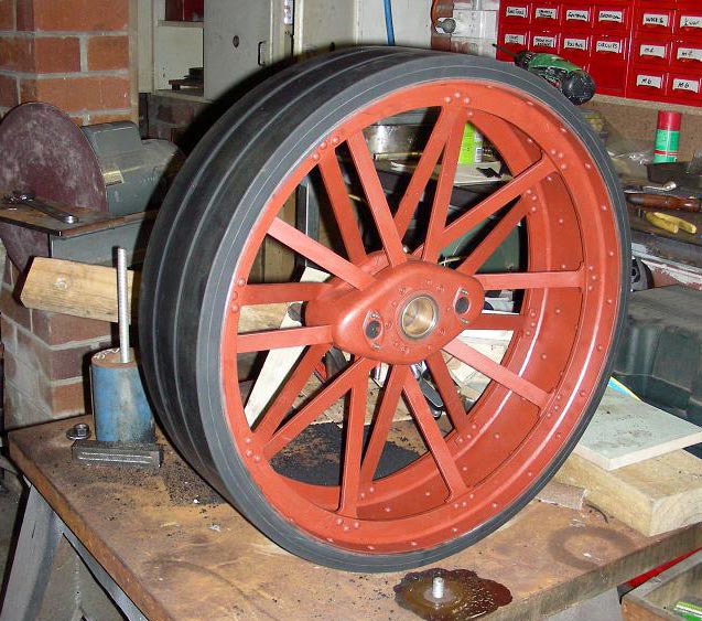
Traction Engine Wheel
Fully assembled wheel.
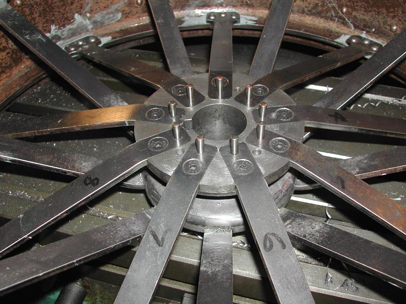
Spokes Secured in the Hub
This becomes hidden by fitting the outer portion of the hub. Only a joint line is visible, with the spokes disappearing inside.
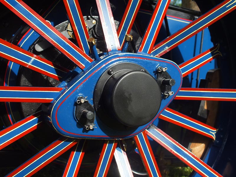
Finished Wheel and Spokes
The wheels were quite awkward to access due to the small spaces between the spokes, especially where they converge on the hub. They were painted and lined through a combination of brush work, lining pens, and templates.
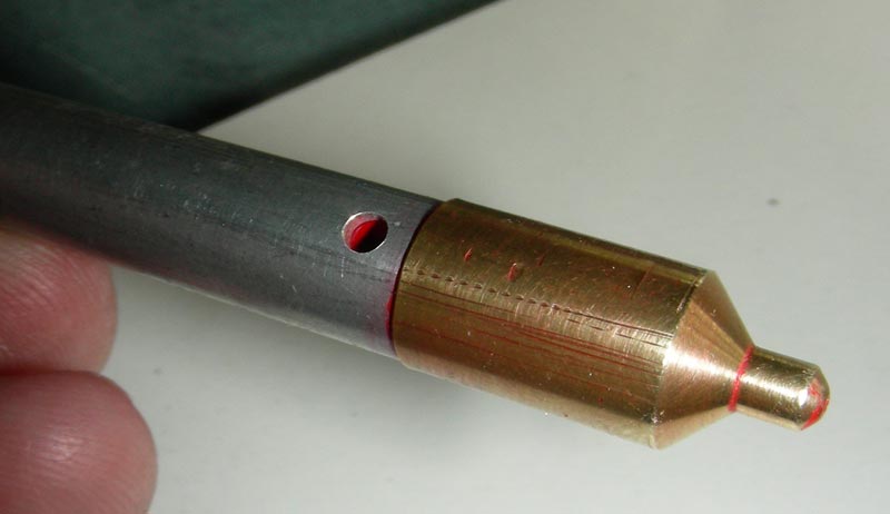
Lining Pen
One of two lining pens developed to provide consistency of line weights.
Lock Box
Lock box with coin for reference.
Drain Cock Bodies
Beginning to fabricate the cylinder drain cock bodies.
Drain Cock Body
First step in machining the bodies.
Drain Cock Body
Reaming the tapered bores.
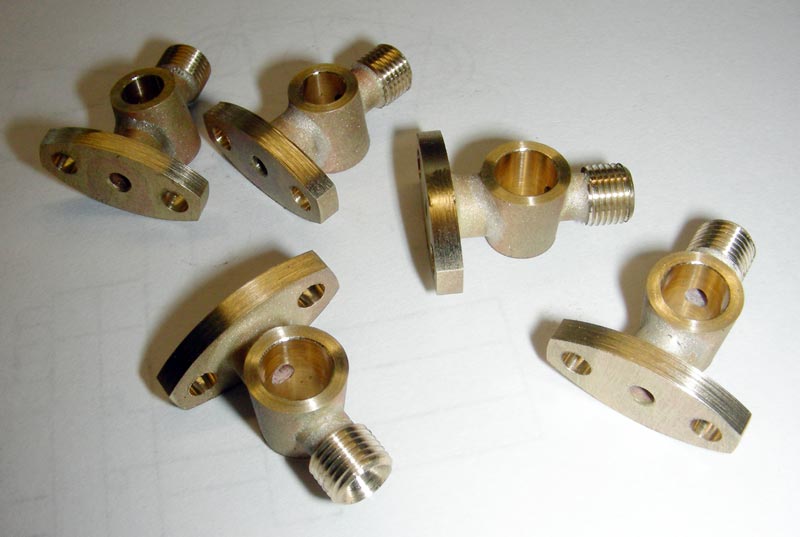
Drain Cock Bodies
Completed bodies.
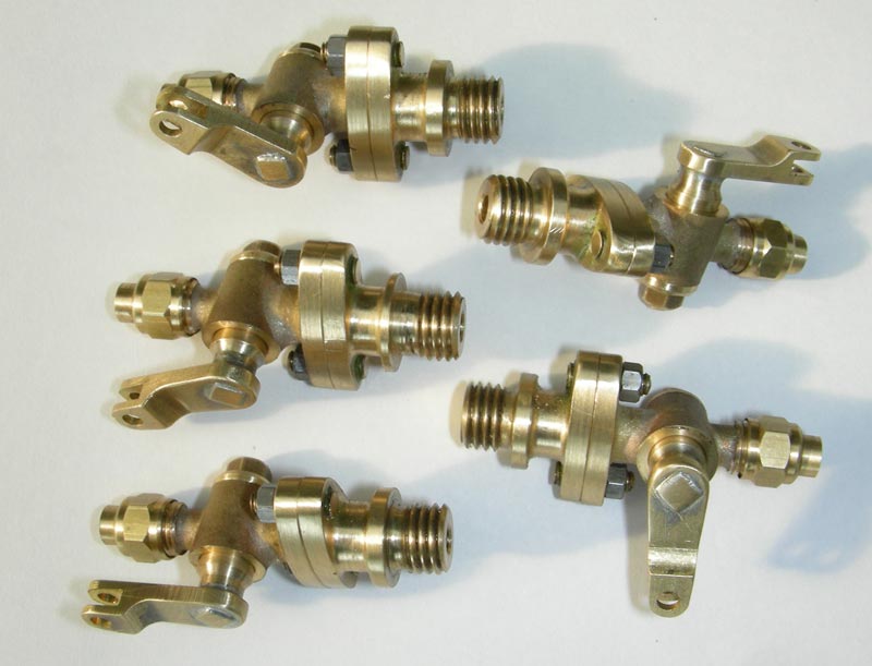
Completed Valves
Completed valves with operating arm and mounting piece. This represents about 30 hours of work.
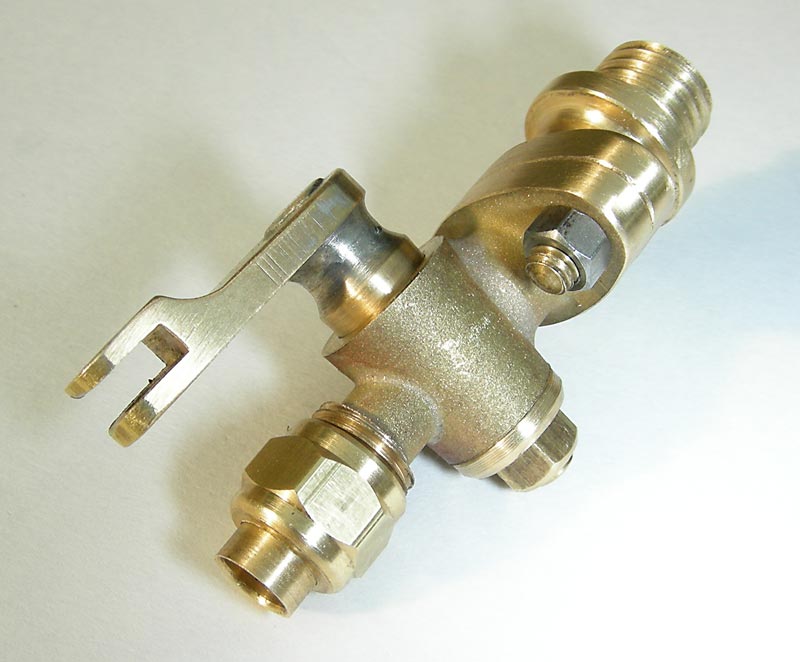
Finished Drain Cock Body
A close-up of a finished body. Length is about 20 mm.
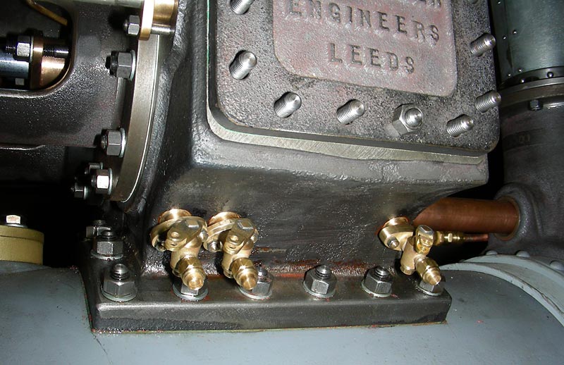
Valves Assembled on Cylinder
The valves assembled on the cylinder. A common rod will move all three simultaneously.
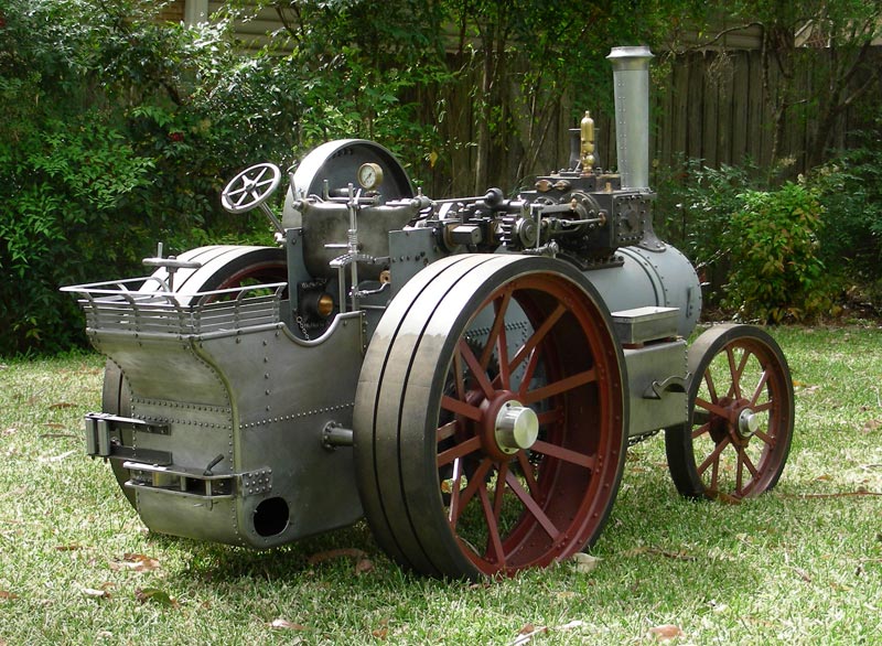
Traction Engine in Progress
The Traction Engine as of January, 2010. Getting to this stage took about 5 years of part-time work.
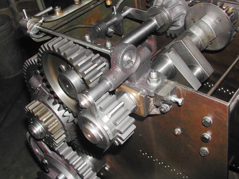
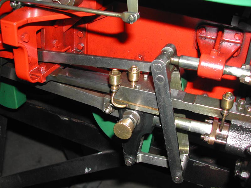
Traction Engine Drivetrain
The drivetrain consists of 6 DP and 7 DP spur gearing, via four transverse transmission shafts, including the crankshaft and the rear axle. A bevel gear differential is fitted to the 3rd shaft (lower left), and each rear wheel has a separate final drive. Three changeable gear ratios are provided, each with mechanical interlocks (rods visible top left), to prevent engagement of more than one ratio at a time. Top speed for the model is 3 mph at 400 rpm.
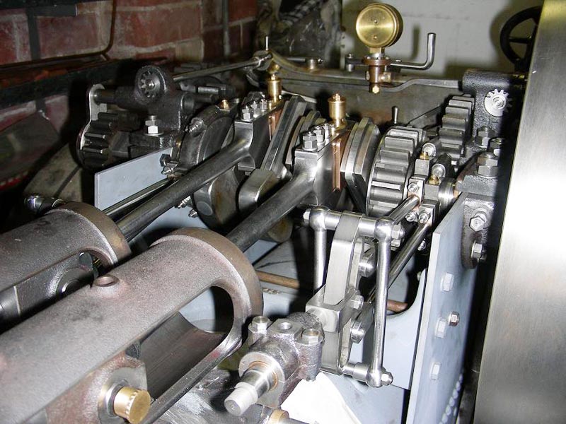
Traction Engine Drivetrain
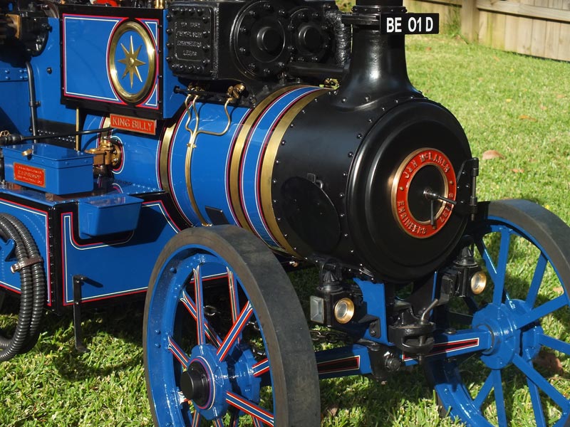
Finished Traction Engine
A front view of the finished traction engine.
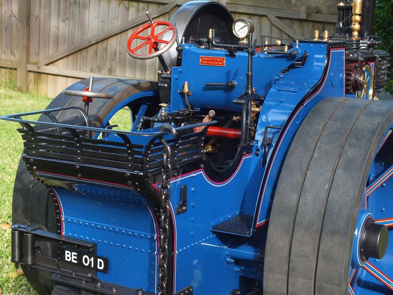
Finished Traction Engine
Finished Traction Engine
Other Projects
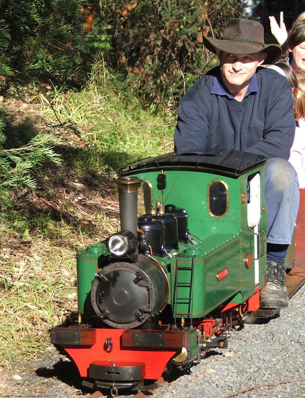
Ross Driving His Fowler
The Fowler is a 2-ft gauge contractor’s locomotive.
The Fowler
This locomotive was originally employed on sugar tramways in Queensland, Australia.
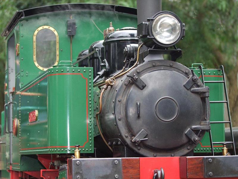
Fowler Close-Up
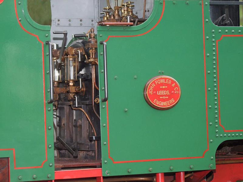
Fowler Cab Close-Up
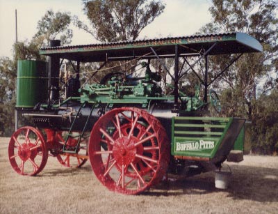
Buffalo Locomotive Restoration
A full-size restoration of the Buffalo.