We are fortunate to have received a large amount of photos detailing Lou’s incredible craftsmanship, with captions contributed by Lou himself. We hope that this will provide an added opportunity for fellow craftsmen to learn from one of the greats. Click on images to enlarge.
The 1/6 Scale Duesenberg Project
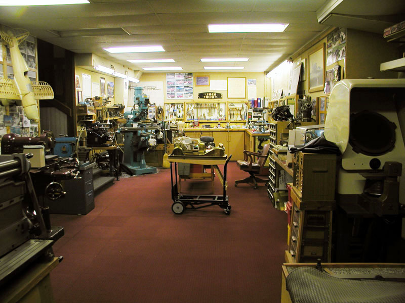
Lou’s Home Workshop

Lou’s Home Workshop
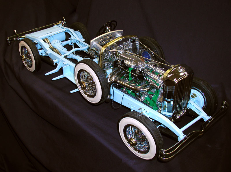
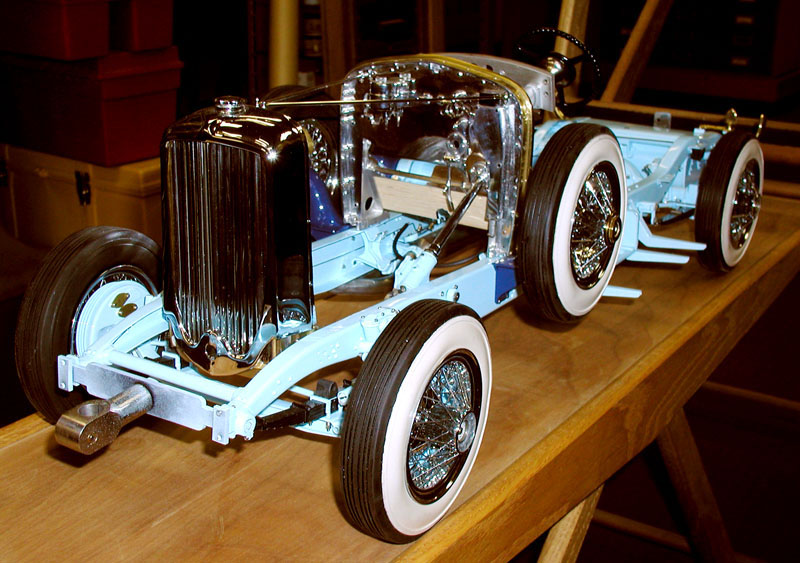
Duesenberg Chassis
A 3/4 view of the chassis, at 1/6 scale, so it’s about 38” long, and weighs 40 lbs. This scale results in an engine of about 2 cu. in. displacement. Square and cubic laws change things dramatically. 6 cubed is 216, and divided into 420 (in full-size) is about 2 cu. in. Frictions are much higher than full-size, but somewhat compensated by lower inertia.
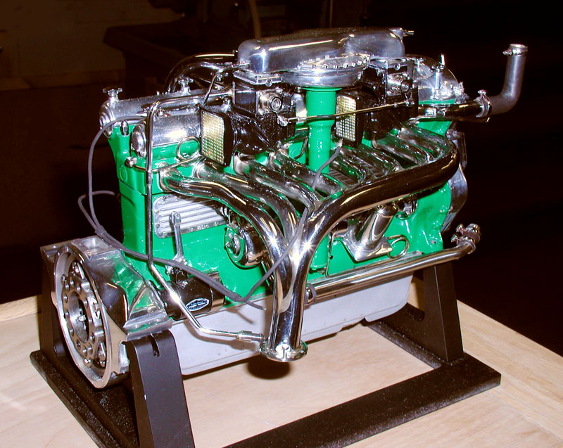
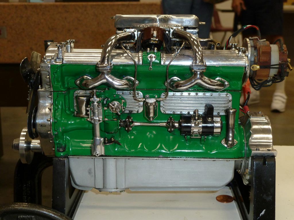
Duesenberg Engine—Exhaust Side
The engine’s exhaust side, with its beautiful 8-branch manifold. Carburetors have barrel throttles—the front one has a small Venturi for idling, and the furthest rear carburetor has a much larger one which is progressively linked. The barrels move outward when rotated to open their jets farther for acceleration. The intended fuel is propane. (Non-scale fuel lines can be seen leading off the engine.)
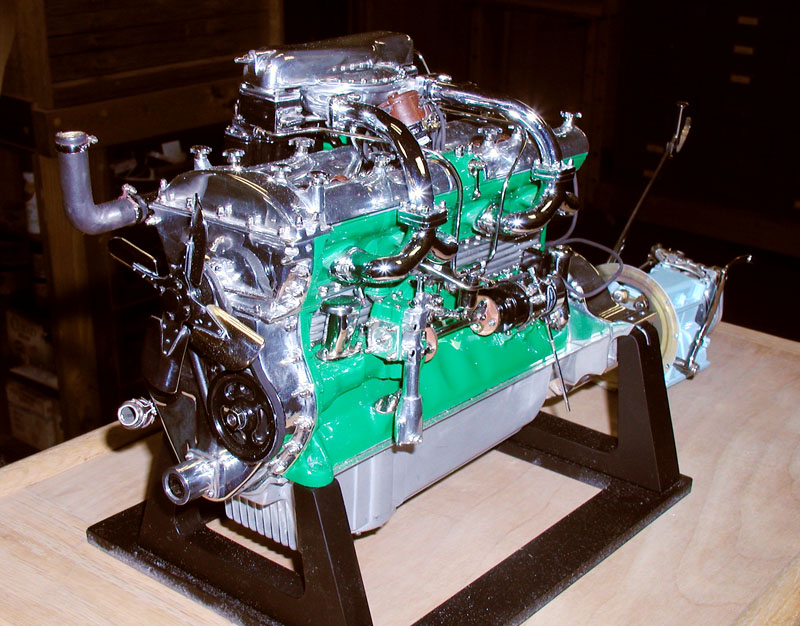
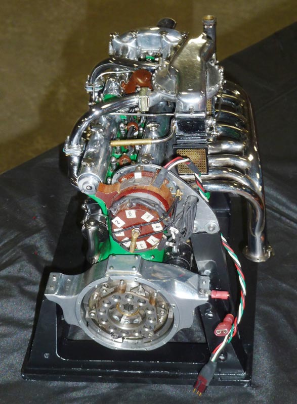
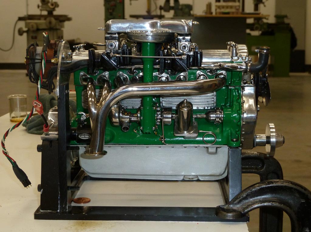
Duesenberg Engine—Intake Side
The engine, seen here from the intake side, shows features such as the Y-branch intakes—chosen simply because they look nice. Ignition points are in the generator to keep the distributor within scale. Its block started as a 38 lbs. chunk of grey iron—it weighs 4 lbs. now.
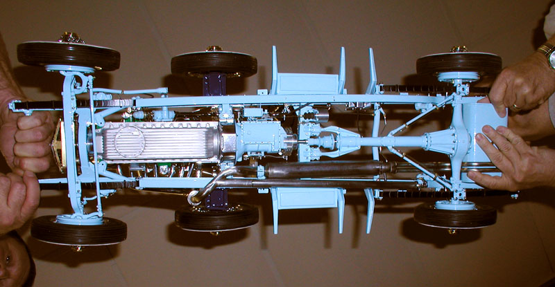
Chassis Underside
Lou likes this photo. Scale is indicated by the hands holding both ends.
Duesenberg Trial Assembly
The fitting on the front of the frame is an attachment for a rotary fixture.
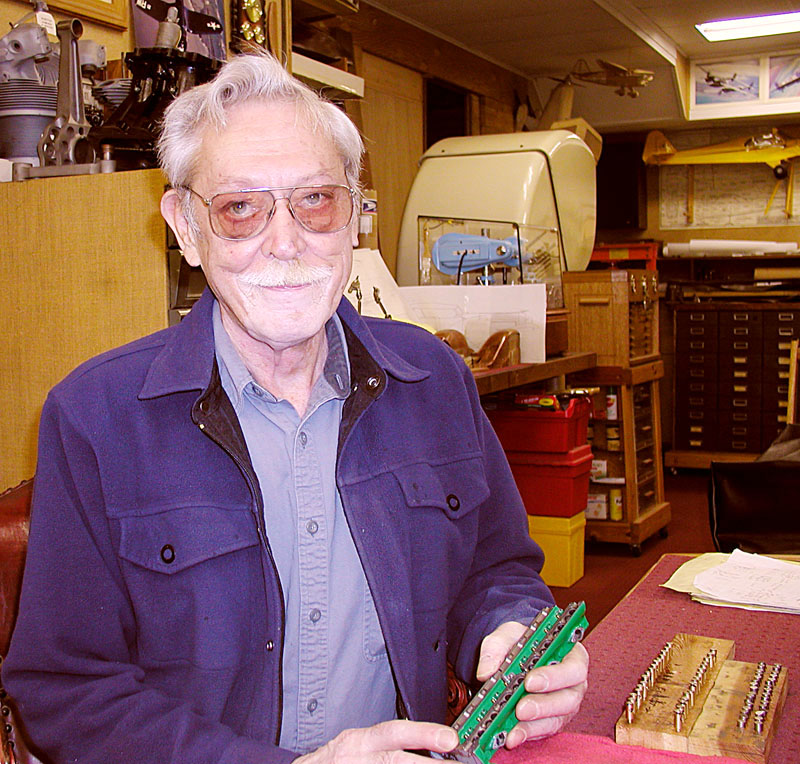
Lou in His Shop.
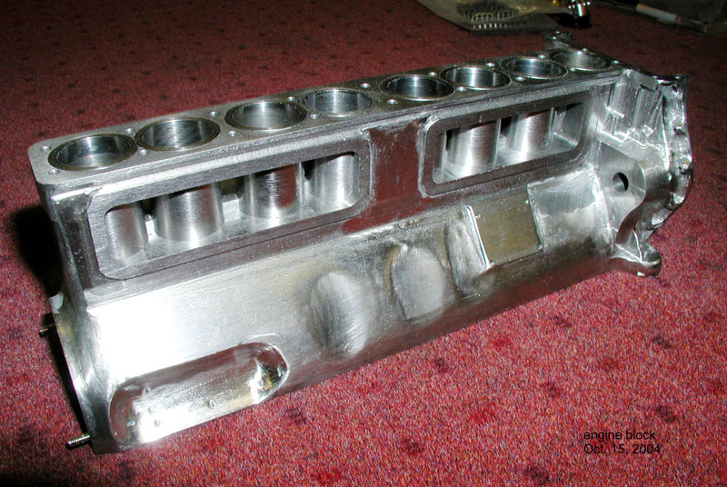
Engine Block Progress
The block after 4-5 weeks of attention. Most components in the model are of the same material existing in the prototype, hence cast iron here. It was decided to fit cylinder liners in order to cut water passages. Liners were turned from Cummins Diesel engine valve guides, a very tough grey iron. Piston rings are also from Cummins valve guides. Two compression rings (.025” thick) and one oil ring (.040” thick) were made.
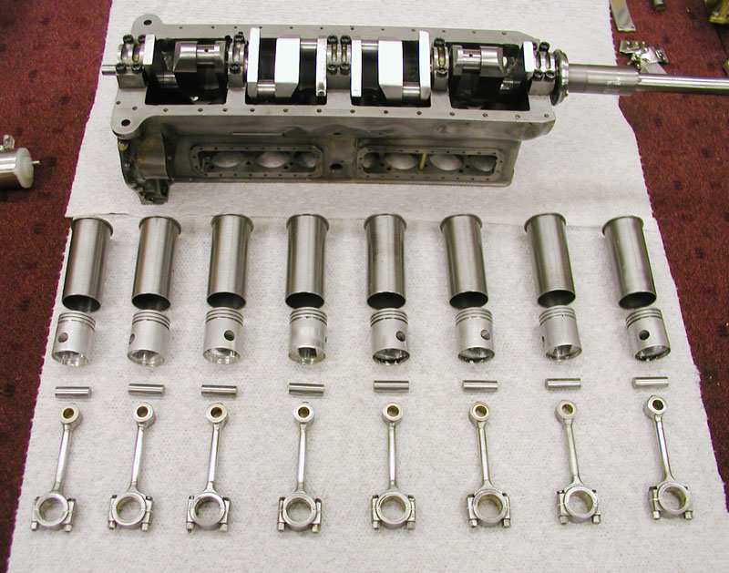
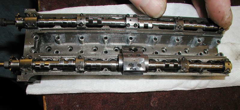
Engine Block Internal Components
Internal components for the block. Its crankshaft is 4130 steel; a drive extension is installed to run in bearings which are .010 silver, also used in connecting rod big ends. Bronze bushes are fitted to the pin.
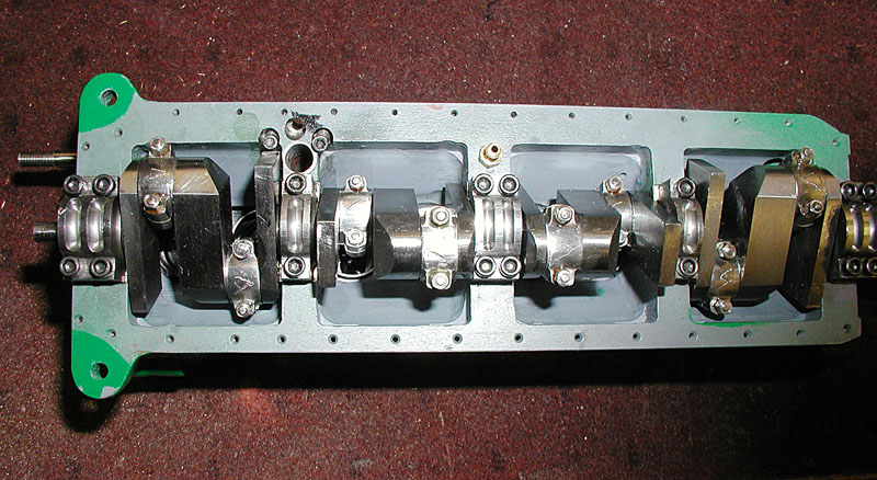
Engine Block Underside
Main and connecting rod big end bearings are silver; crank is 4130 steel.
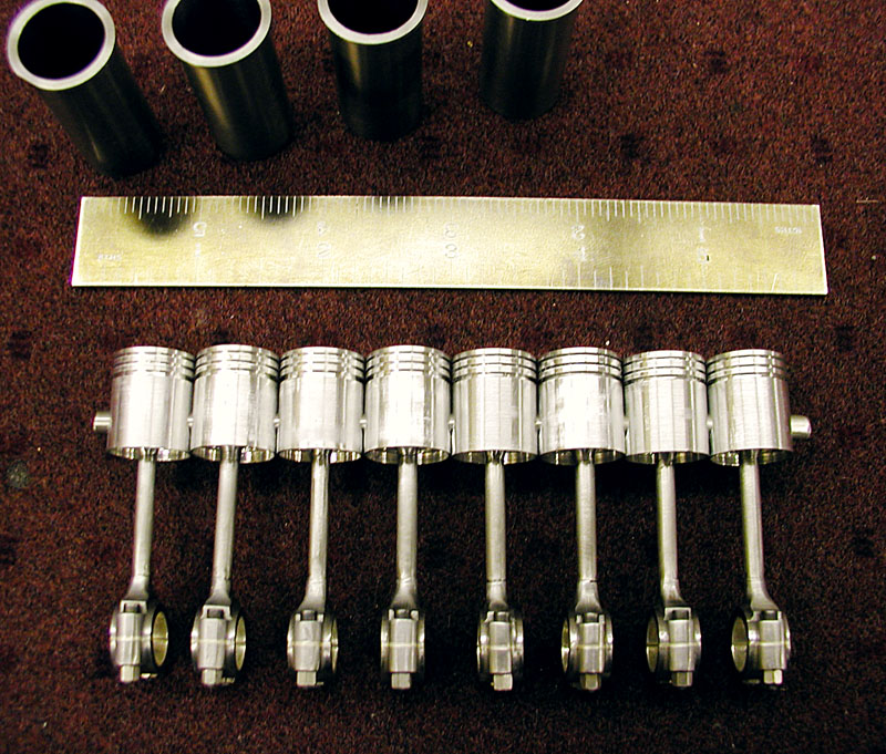
Piston Assemblies
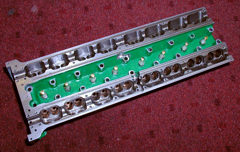
Engine Block Progress
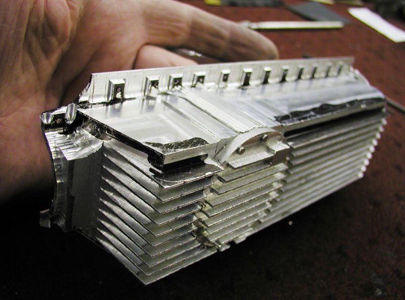
A highly ventilated lump of cast iron—338 holes and milling operations, plus lapping cam bearings, and all those valve seats! The spark plugs are from stainless steel with a Corian insulator.
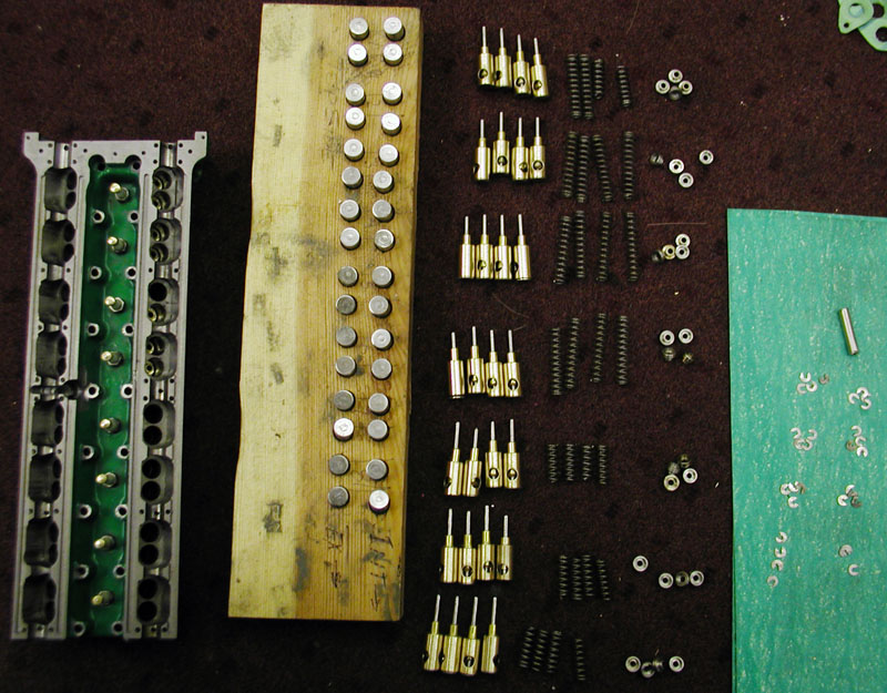
Engine Components
32 Cam follower, 32 “C” clips, 32 keepers, 32 springs, etc. Lou said, “I think I’m going to cry.”
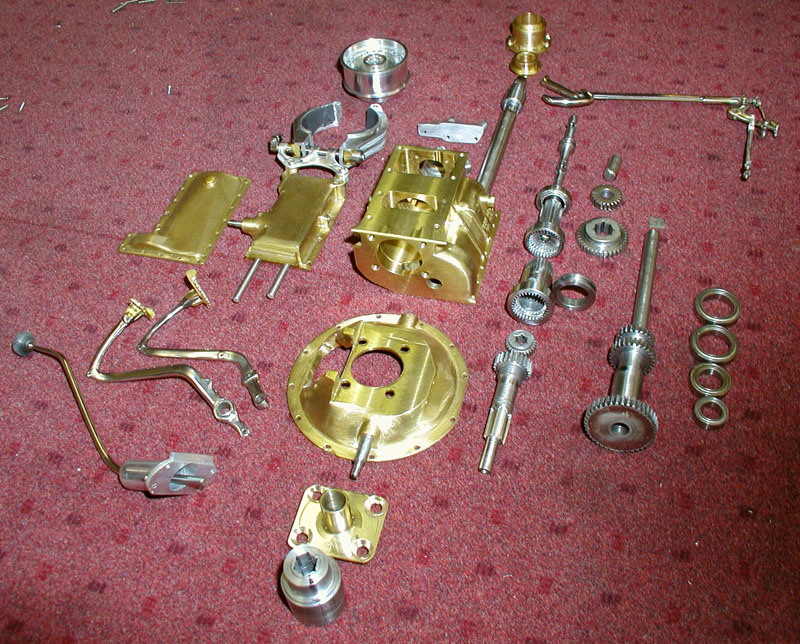
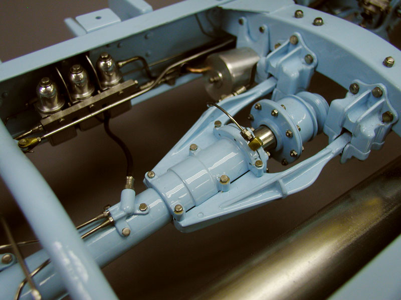
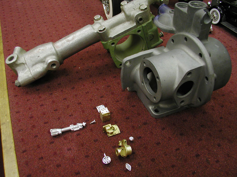
T-72 Warner Transmission
A T-27 Warner transmission in 1/6 scale. Designing such an assembly is a good example of nature not being very scalable. Dividing full-size bearings by 6 doesn’t agree with any listing of miniature bearings, therefore bores and shaft diameters are changed as necessary. This cannot be allowed to interfere with the gears, which are kept to 1/6 scale exactly so the centers and ratios are correct. Full-size diametrical pitches are multiplied by 6, from which the small gears are calculated. Special cutters had to be made at 60 Dp and 48 Dp, along with a shaving tool for the compound set of internal gears used in the second gear position.

Rear Axle With Components
The differential contains 4 bevel gears which are hidden inside their cage. Many trials were required to cut the ring and pinion. Hypoid gear cutting requires solving equations for 13 degrees of freedom if a Gleason machine is available (a small one)! Only trial and error, and finally filing tooth entry profiles, could be used in my shop. The banjo housing is cut from one piece of steel.
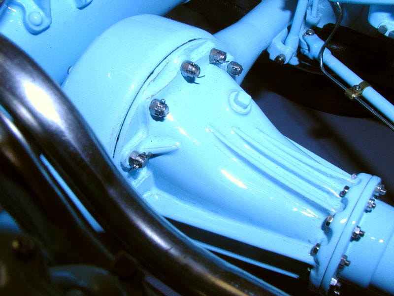
Differential Housing
While many parts appear to be castings, none are. The differential housing is a typical build-up from pieces that were silver brazed together. Castellated nuts were machined, polished, and fitted with .015 diameter cotter pins.

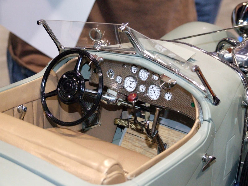
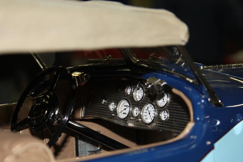
Instrument Panel
The damascened instrument panel, or engine turned stainless steel. This was not particularly difficult, but took about 5 hours with the milling machine and its digital read-outs. Steering wheel controls do work.
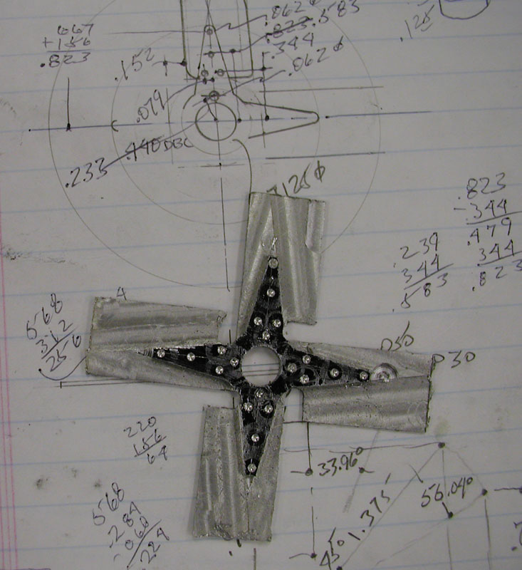
Rough Fan Sketch
Lou’s rough fan sketch—no formal drawings exist. Layouts such as this are drawn out if complicated, but mostly consist of freehand sketches.
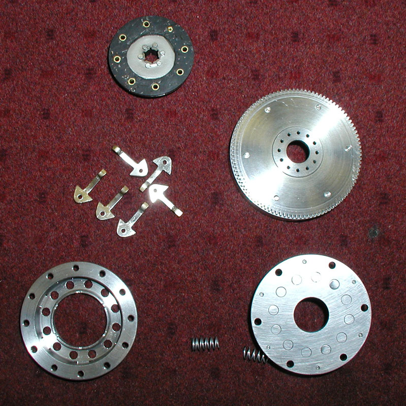
Clutch Components
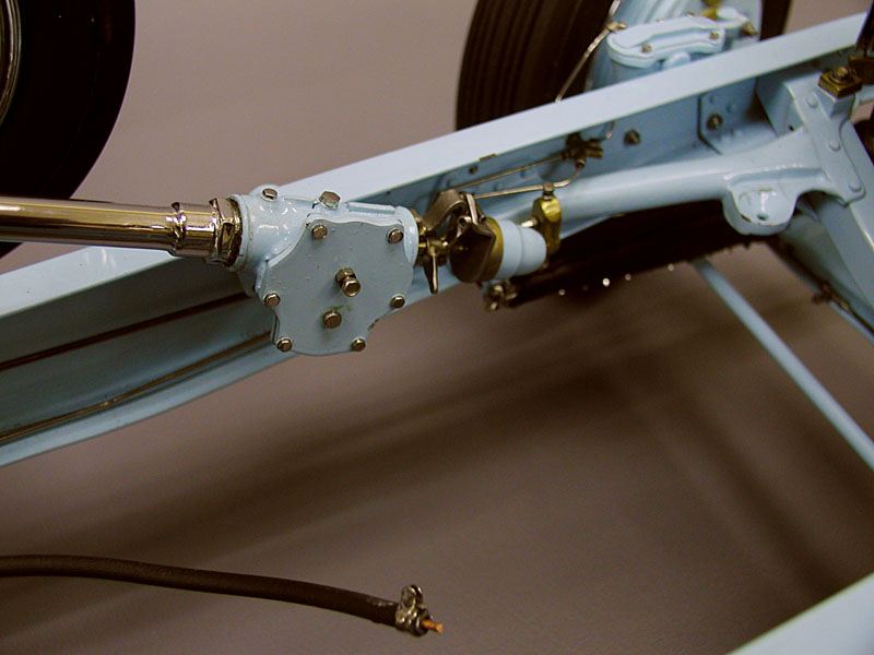
Steering Column
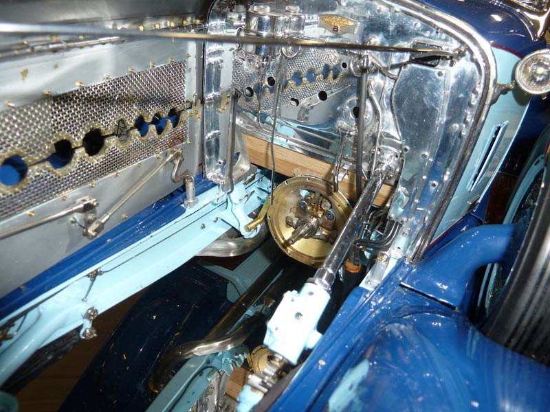
The steering box and levers for throttle, spark retarding, and lights—altogether 42 parts make up the steering column. Also visible is the left side front engine mount, a highly contoured part made from solid steel then bolted and riveted to the frame.
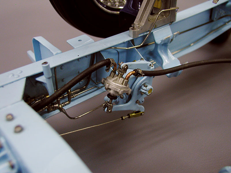
Servo and Brake Master Cylinder
This is a very modern design, especially if compared to Rolls-Royce’s contemporary use of a very complex mechanical servo.
Fuel Pumps
Electric fuel pumps backed up the engine’s mechanical one.
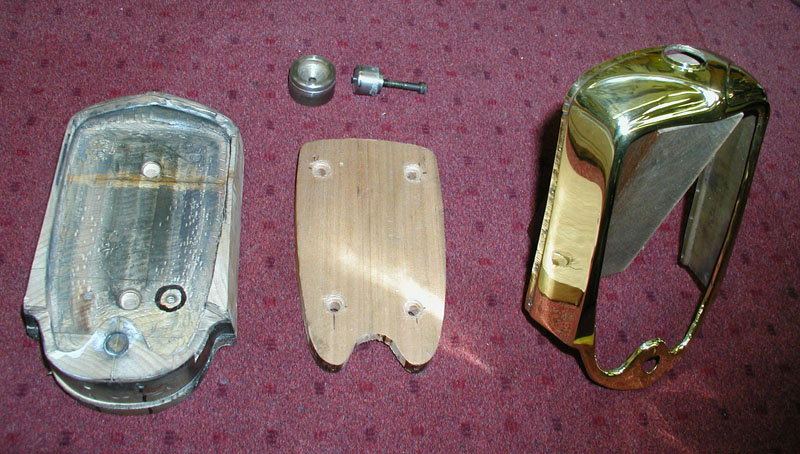
Radiator Shell and Tools
The radiator shell and tools, cherrywood buck, punch and die for the neck, and .015 brass.
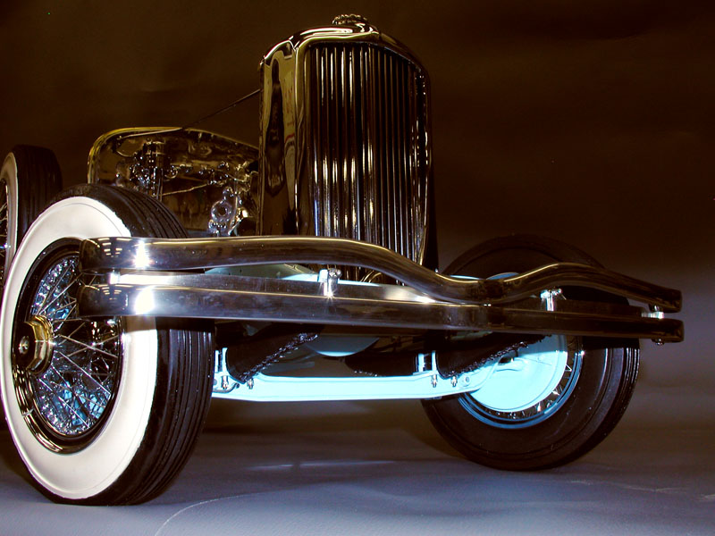
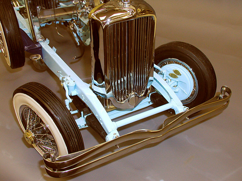
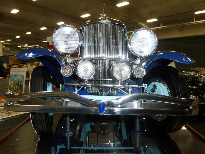
Duesenberg Front End
Bumpers required about a week of work—half of which was spent preparing stainless steel, and making bending jigs, forms, and a fixture to keep the bolt centers exact. All bending was at red heat, and even then stainless steel will still have springbuck which complicates the issue.
Radiator Shell Detail
The radiator shell was made from brass sheet. This was bent over a cherrywood buck, or form, with a rawhide mallet, then a planishing hammer. It was then filed, sanded, polished, and chromed. Not being experienced in this skill, I ruined 8 blanks before finishing this one.
Fuel and Chassis Pumps
The fuel pump and chassis pump with their full-size equivalents.
Firewall Machining
The firewall being machined, which took about 40 hours.
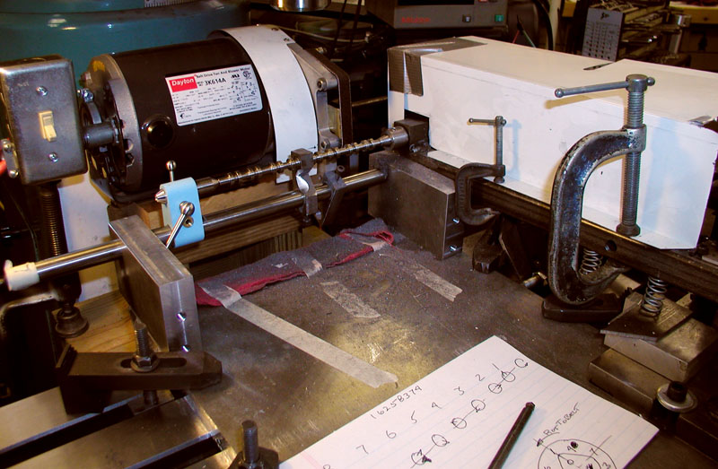
Cam Grinding Lash-Up
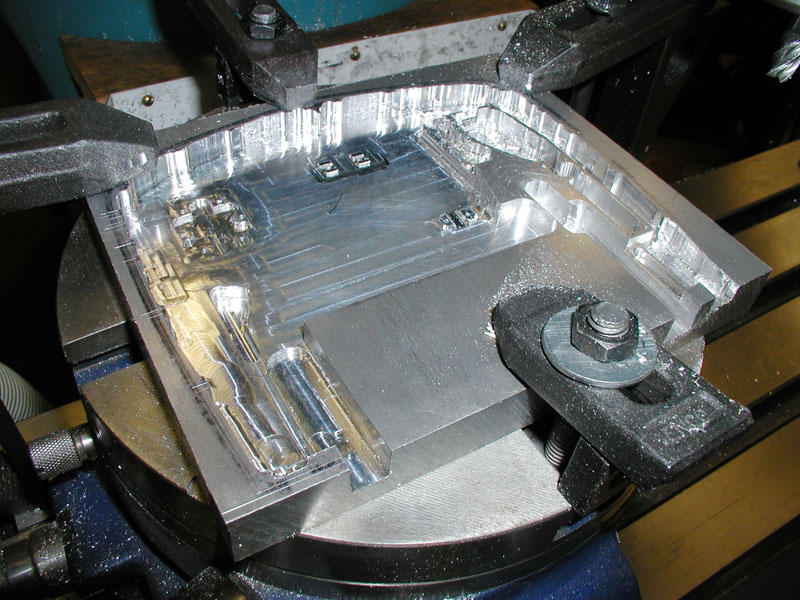
The Machined Pan

Oil Pump
Gears are 13 teeth, 1/4 diameter. It pumps 8 psi, and will be relieved to 3-4.
Lapping Cams
Cams used a garnet compound because it doesn’t imbed. Cams are from tool steel, drilled 1/8 dia. through (7 in.). Four sets were attempted due to set up trials and foolishness.
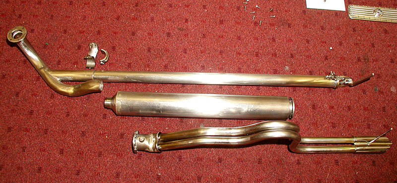
Exhaust System
The exhaust system is made of stainless steel.

Operator and Over-Center Linkage
The operator and over-center linkage for the supercharged car exhaust cut-out.
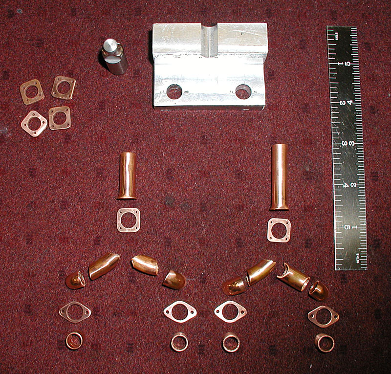
Intake Manifold Components
The intake manifold parts are copper, and consist of 9 pieces each.
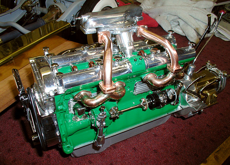
Intake Manifold Fitting
The manifold is mounted for fitting on the engine.
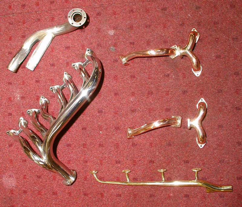
Manifold and Exhaust Components
These are all the manifold and exhaust parts. Four special tube benders were made, the exhaust is stainless steel, the water manifold is chromed brass, and intake pieces are copper.

Paper Pattern for Front Fenders
Lou noted, “Ya gotta start somewhere!”
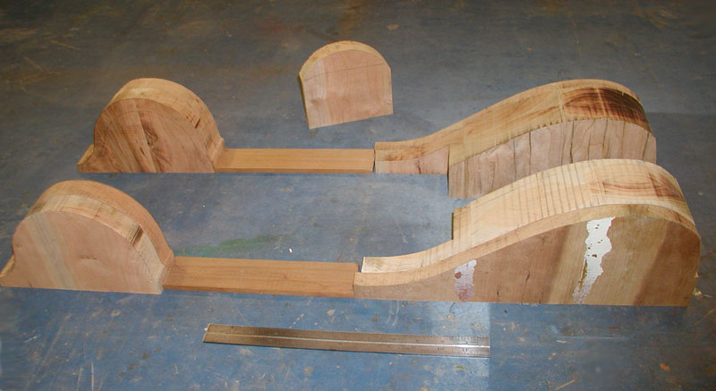
Forming Bucks
Cherrywood forming bucks were bandsawn to shape.
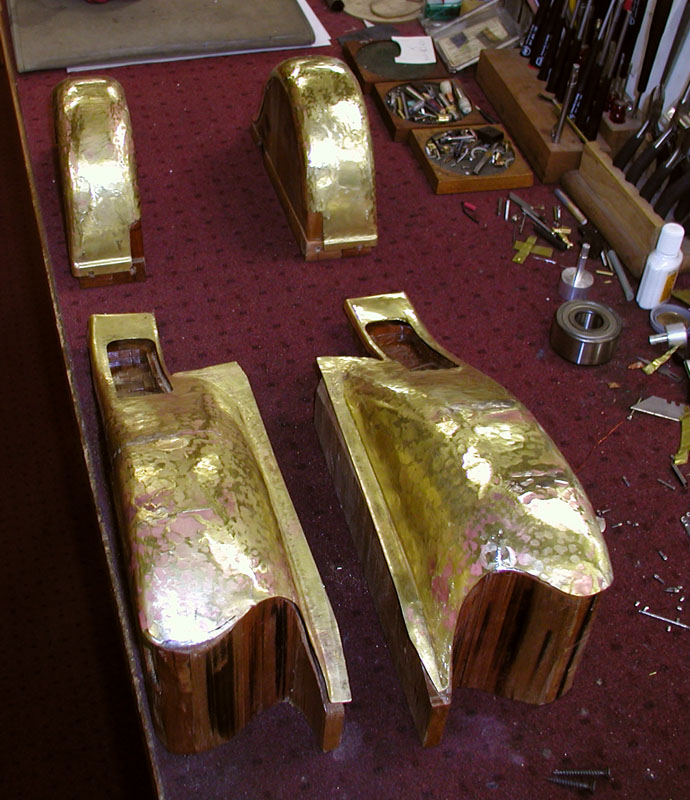
Fender Bashing
First fender bashing—the ugly stage!
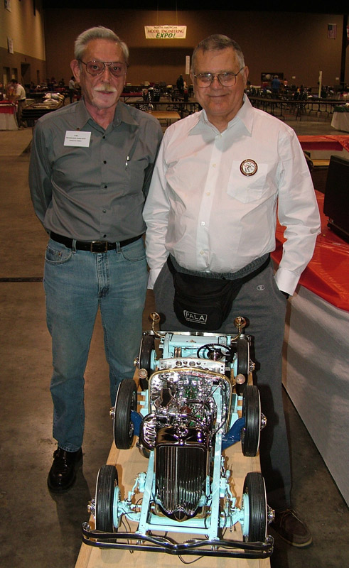
Lou Chenot and Joe Martin at the NAMES Expo
Lou Chenot (left) and Joe Martin talk at the end of the 2007 NAMES Expo in Toledo. Lou was loading up the Duesenberg to head home, and had stopped to talk to Joe as they both watched Pierre Scerri’s Ferrari model being photographed for an upcoming magazine article.
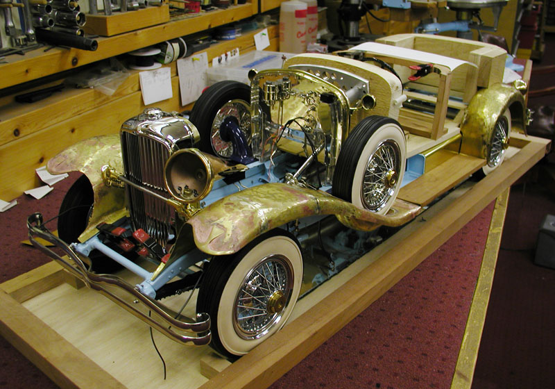
Chassis Progress
Initial sheet metal fitting to the chassis.
Duesenberg Progress (2008)
These photos were from February, 2008, with the bodywork coming along nicely. This level of progress represented almost a year of work since the 2007 NAMES Expo (see picture with Joe Martin above for reference).
Duesenberg Progress (2008)
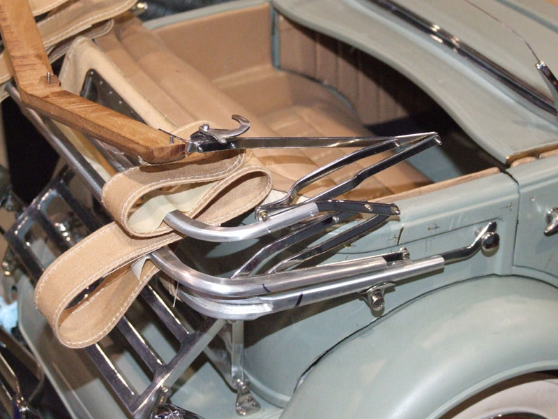
Top bows and irons were made in a single plane study, adjusting hinge points until folding could be accomplished. They were then copied in stainless steel. Technically speaking, the mechanism is a triple set of unequal arm 4-bar linkages.

Duesenberg Progress (2008)
The windshield was made from 11 individual components. It would go on to contain glass that is .8 mm thick.
Duesenberg Progress (2008)
Fitting the hinges, windshield, etc. to the body contours was a time consuming process. The doors now make the proper “click” when closed, and the vents work.

Duesenberg Progress (2008)
Running boards are cherry wood to simulate English walnut, yet another example of nature not always being scaleable. Installed in the wood are chrome strips with rubber inserts.
Duesenberg Progress (2008)
Duesenberg Progress (2008)
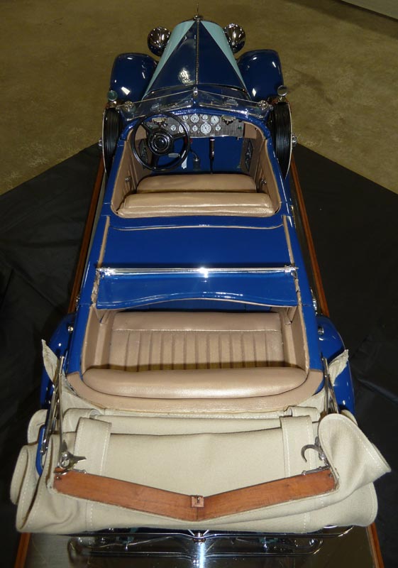
Leather upholstery consists of one entire goatskin sewn as per full scale. In making the interior parts, allowances had to be made for the thickness of the upholstery.

Duesenberg Progress (2008)
The body was still in primer, and would have to be completely disassembled for painting later that year. Some parts still remained to be chromed.

Duesenberg Progress (2009)
These next photos were taken in April, 2009 at the NAMES Expo in Toledo, OH. The bodywork was almost complete, and was primered and ready to paint.
Duesenberg Progress (2009)
Lou had since removed the engine, and it went back on the test stand for final modifications to get it running. Once the engine was running, and ready for re-installation, the final two-tone blue paint job was applied.
Duesenberg Progress (2009)
Lou waited until the last minute for final painting to minimize the chance of scratching the paint during the labor-intensive engine installation process.
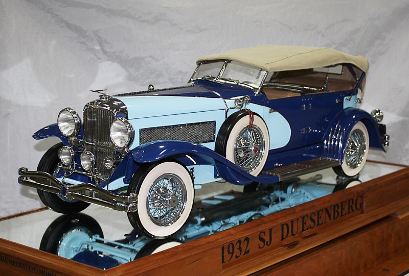
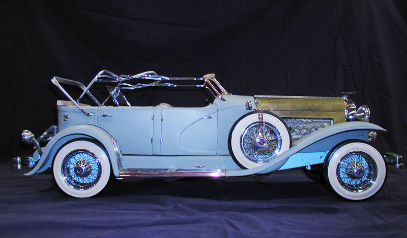
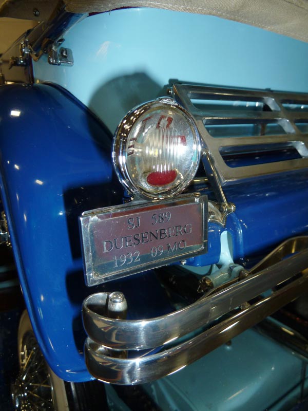
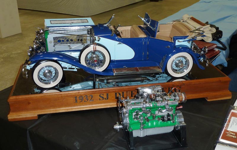
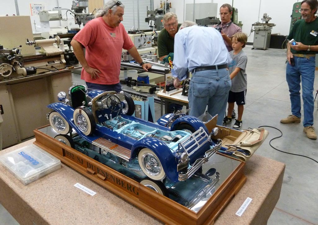
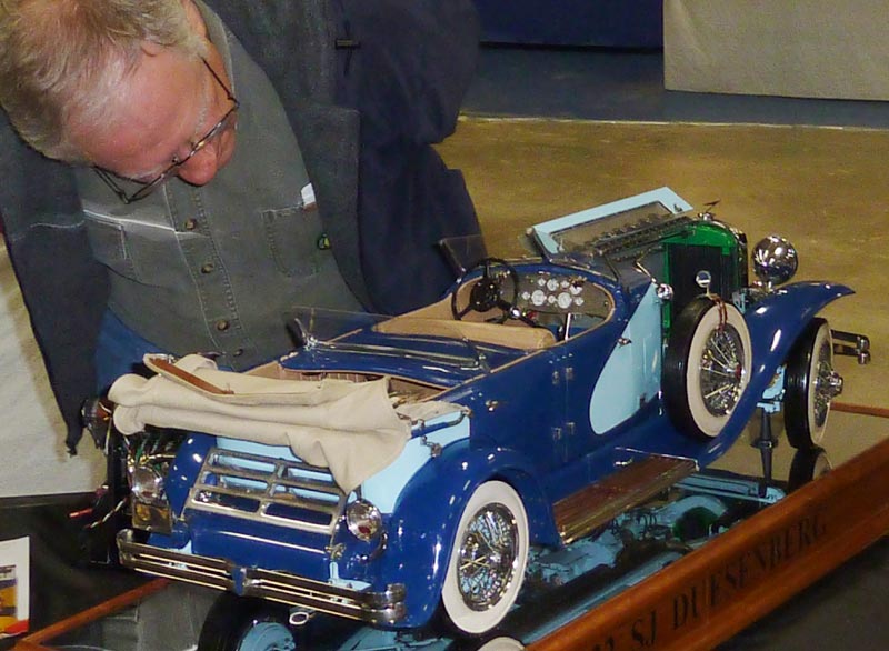
1/6 Scale 1932 Duesenberg
Shown here at the 2010 NAMES Expo, the model was finally in complete and painted form. The engine was not installed at the time, as it had just been successfully run on the test stand. At this stage, all components were completed, and further work was scheduled to be done on the engine to get it to run on gas, instead of the propane which was first used for test running.
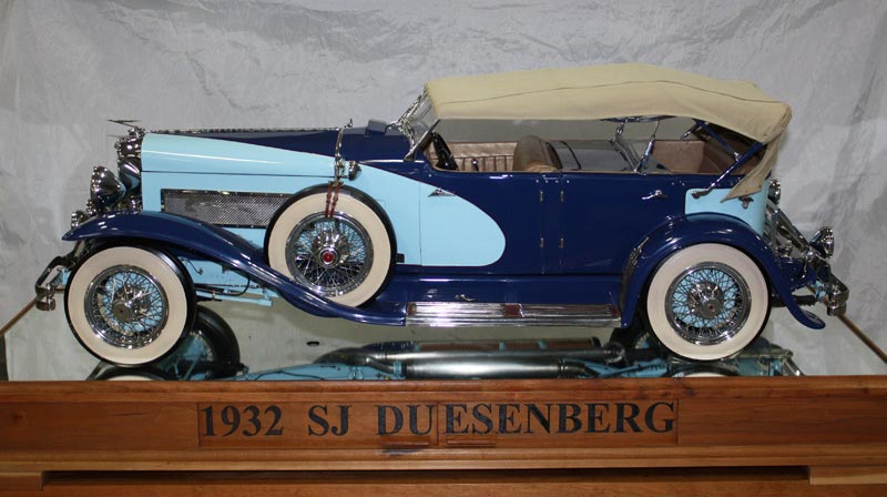
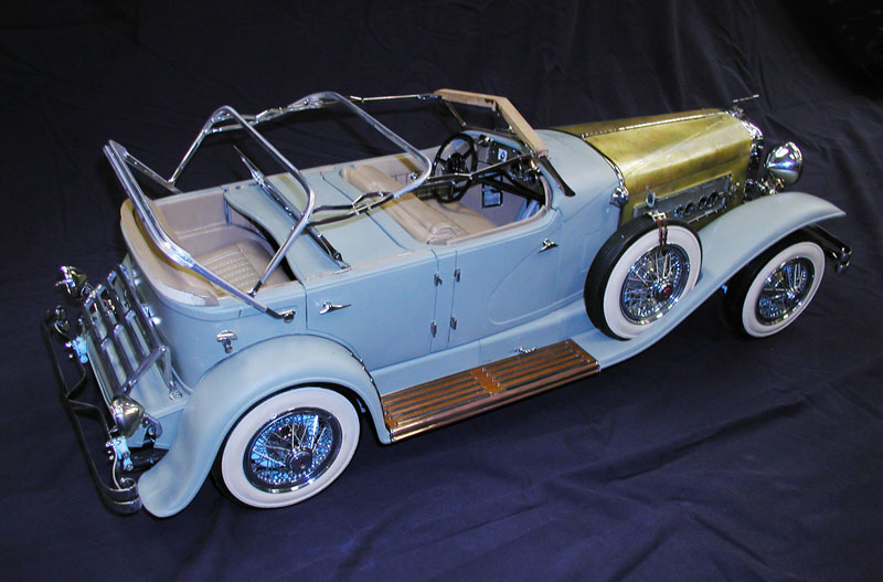
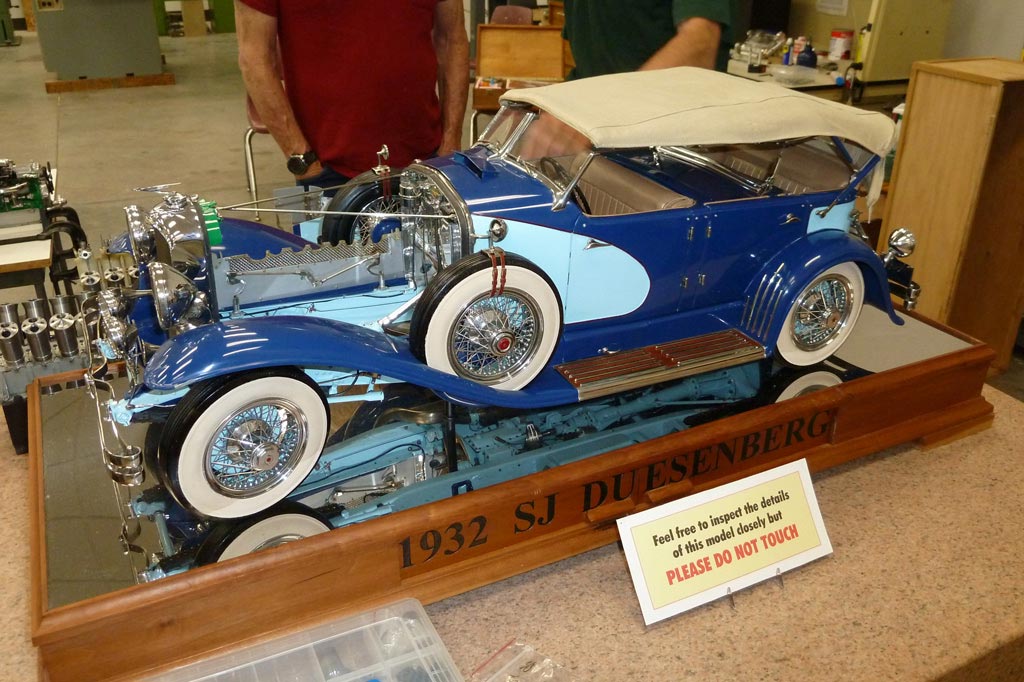
Finished Duesenberg (2010)
The two-tone blue car is every bit the masterpiece that the original cars were, with the additional challenge of building each part in miniature.
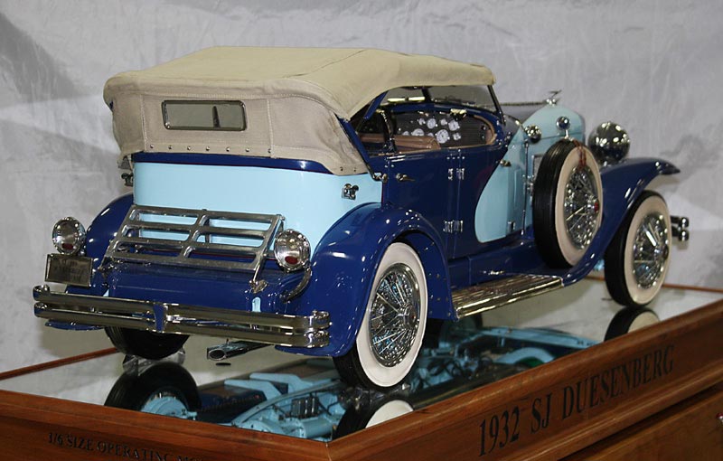
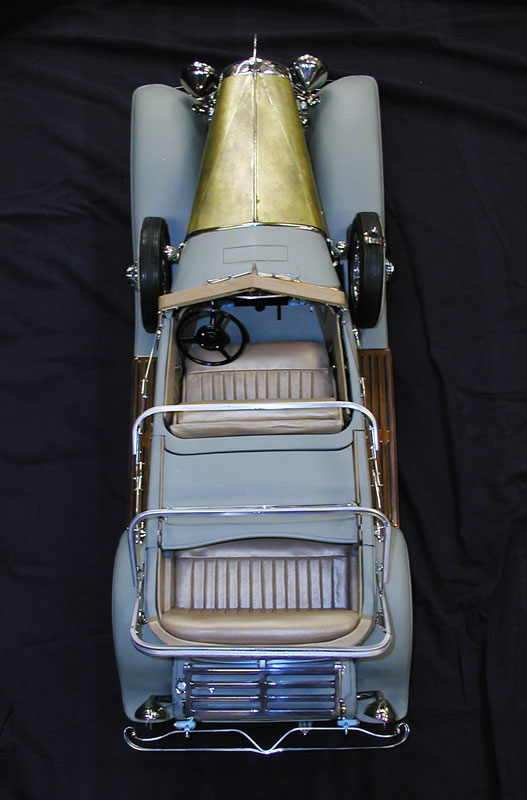
Finished Duesenberg (2010)
Once the engine was running, it was shown at model engineering shows in York, PA, and Southgate, MI, in 2011. It was then reinstalled in the car. The mirrored wooden display stand was completed as well.
Finished Duesenberg (2010)
Many people got the chance to see the engine running outside the car in 2011. Once it was reinstalled in the body, it would not be run again. Fortunately, the running engine was captured on film for posterity!

Lou Receiving the Craftsman of the Decade Award
At the 2011 NAMES Expo, Lou was presented with the Joe Martin Foundation’s Craftsman of the Decade Award. He received a check for $2000.00, and became the foundation’s 15th winner of the top award.
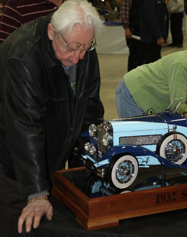
Bill Huxhold Inspecting the Duesenberg
Lou joined a very elite group of craftsmen who have won this award. In this photo, one of those craftsmen, Bill Huxhold, inspects Lou’s model.
Duesenberg Details
Here are additional photos of the Duesenberg taken at the 2011 NAMES Expo, featuring more hidden details.
Duesenberg Details
The engine was still being displayed outside of the car at this point, although it was not cooperating with Lou on this particular weekend.
Duesenberg Details
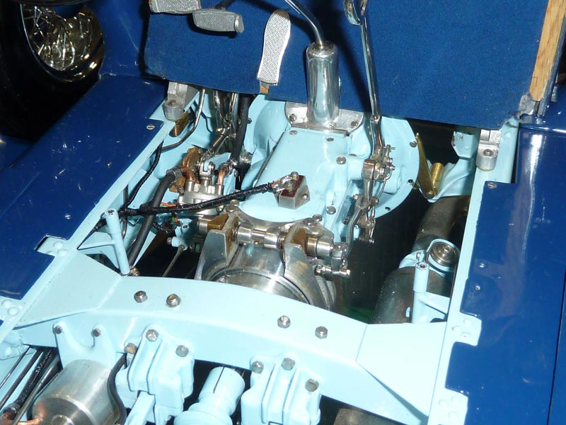
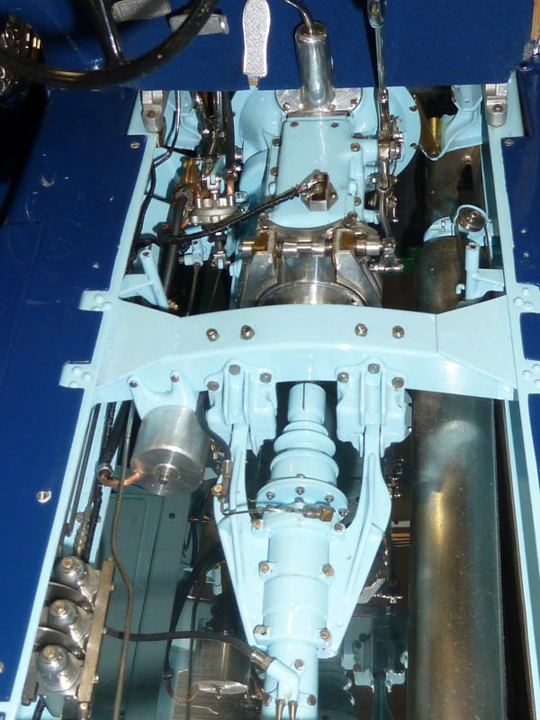
These photos show some of the frame and transmission details that can best be seen when the engine is not in the vehicle.
Duesenberg Engine
Another look at the incredibly detailed finished engine. Show-goers would get one last chance to see the engine outside of the car at the Western Engine Model Exhibition in Pleasanton, CA, in August of 2011. After that, the engine was reinstalled in the car in 2012, and would not run again.
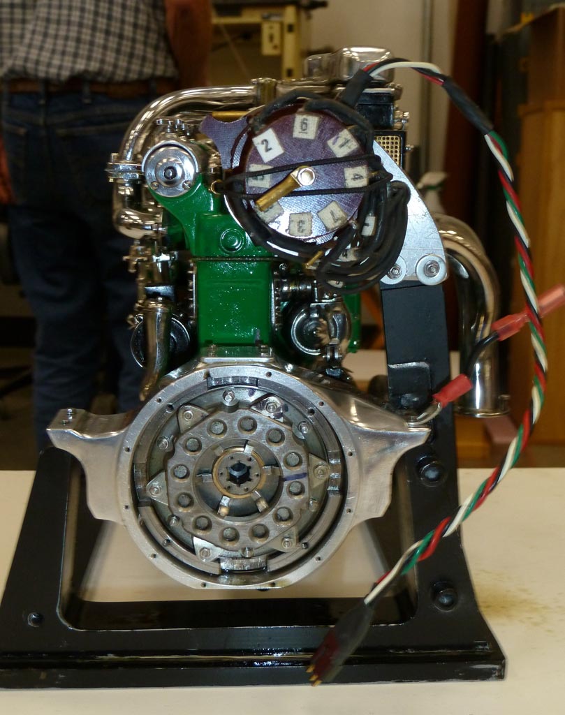
Duesenberg Engine
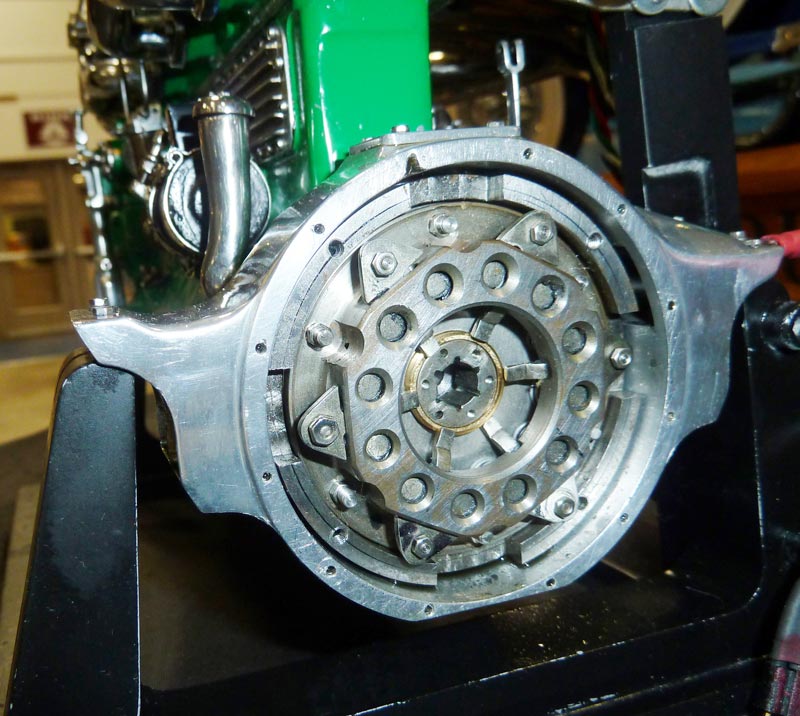
The model Duesenberg’s 1/6 scale Liberty V-12 engine sits outside of the car. These photos show more details of the bell housing and clutch.
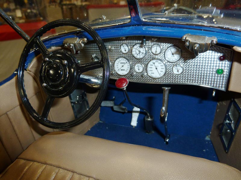
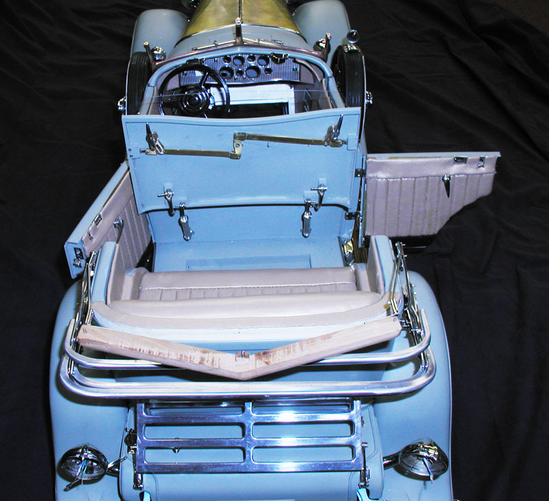
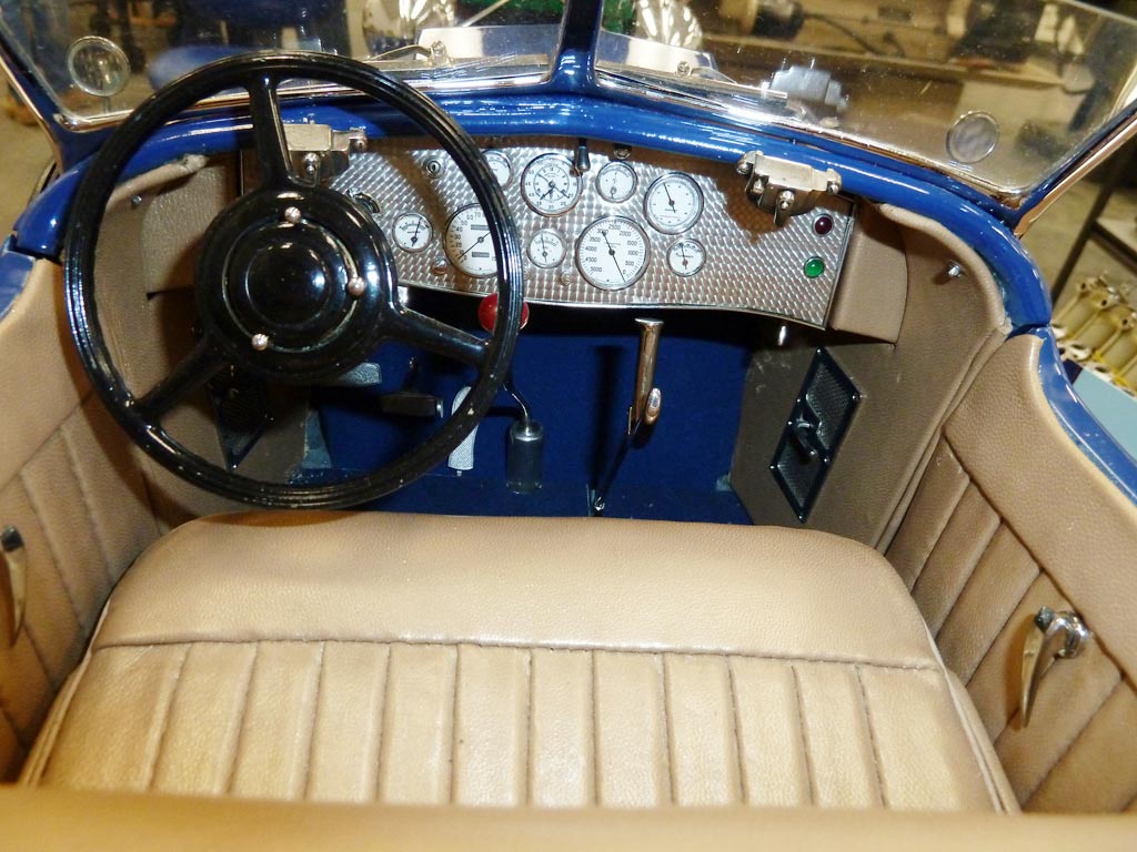
Duesenberg Interior
Here are some close-ups of the interior and dashboard.

Duesenberg Interior
Duesenberg Interior
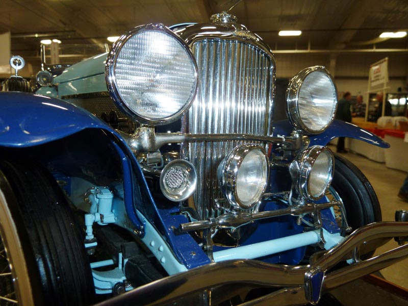
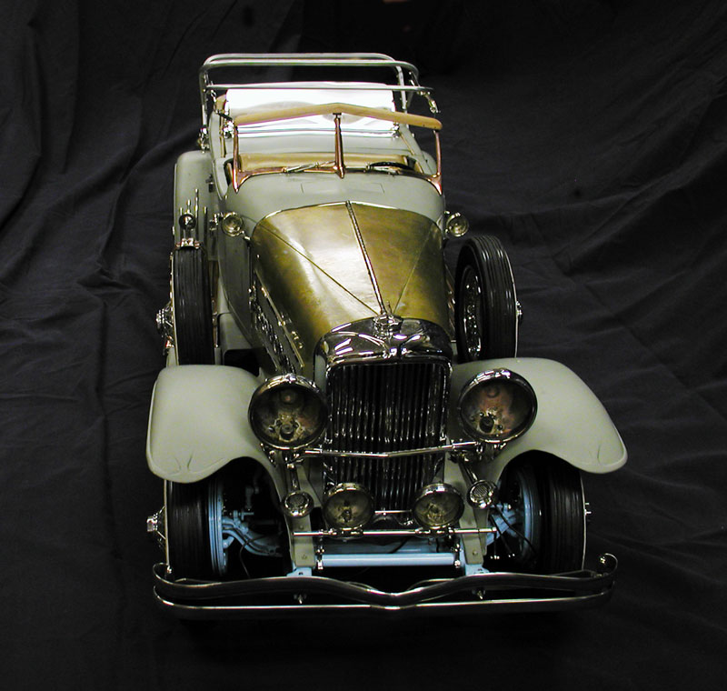
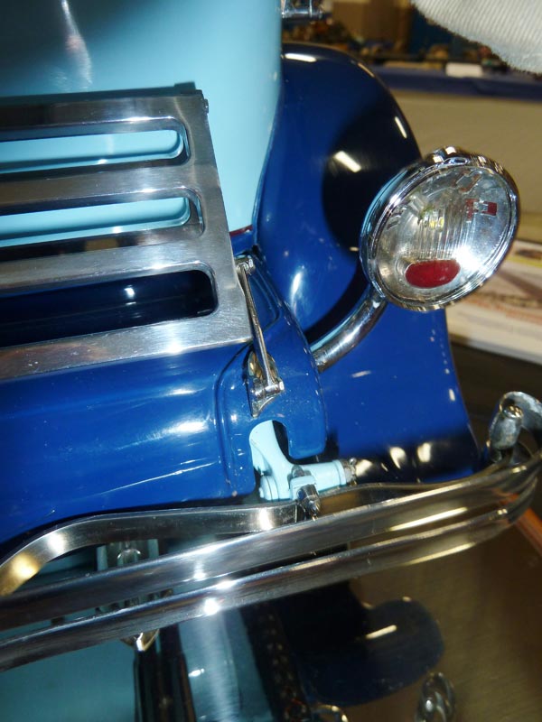
Duesenberg Front End
The following photos show some additional details of the exterior of the car.

Duesenberg Exterior
Duesenberg Exterior
Duesenberg Exterior
The paint job is as flawless as that of a real Duesenberg.
Duesenberg Front End
The Finished Duesenberg
The finished 1/6 scale Duesenberg sits on display with its Liberty V-12 engine in front.
Lou With the Duesenberg on Display
Lou talks to a show-goer at the 2011 NAMES Expo in Michigan. He displayed his Duesenberg and Liberty V-12 engine at the Joe Martin Foundation booth there.
Lou and June at the WEME Show
Lou and June Chenot speak with visitors at the Western Engine Model Exhibition, held at the GoodGuys Nationals car show on August 26-28, 2011. The show brought in many hotrodders who had not seen tiny engines before, and Lou’s Duesenberg was a hit—as always. At this point the car was still being displayed with the engine out, and it was run a few times there.
The Duesenberg at the Miniature Engineering Craftsmanship Museum
On September 2nd, 2011, Lou ran the engine for visitors at the Craftsmanship Museum. This was the last time the engine would be run before going back into the car. Fortunately, there is a video commemorating the event.
The Duesenberg on Display
The car was displayed in the Craftsmanship Museum shop, with the top up and down.
A Show-Goer Examining the Duesenberg

The Duesenberg on Display
This was a great chance for the Southern California public to see the car before it returned to the midwest. Fortunately, this fantastic car would return to the museum for permanent display in 2013!
The Duesenberg on Display
The Duesenberg dash is fully detailed, and the lights work.
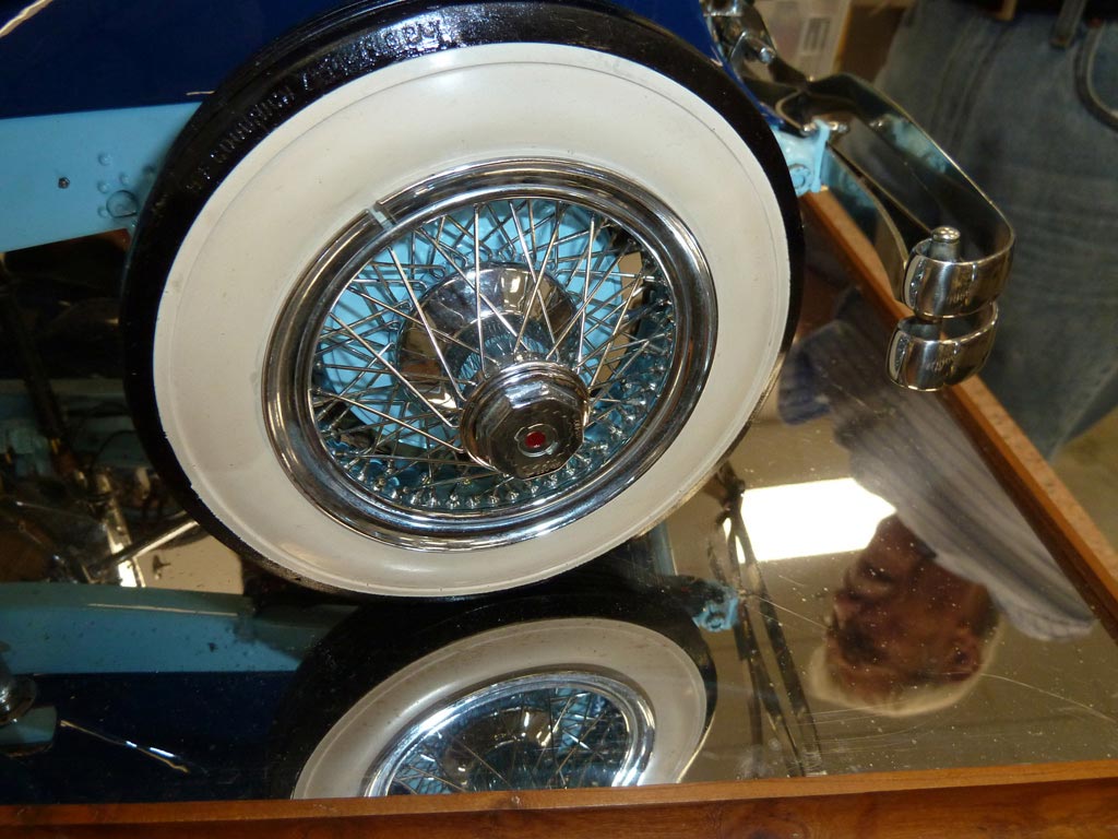
The Duesenberg on Display
In this photo of the wire wheel, Lou can be seen in the reflection of the mirrored display base.

Transmission Bell Housing
With the engine removed and on a test stand, details inside the engine compartment could be easily seen—like this shot of the transmission bell housing.
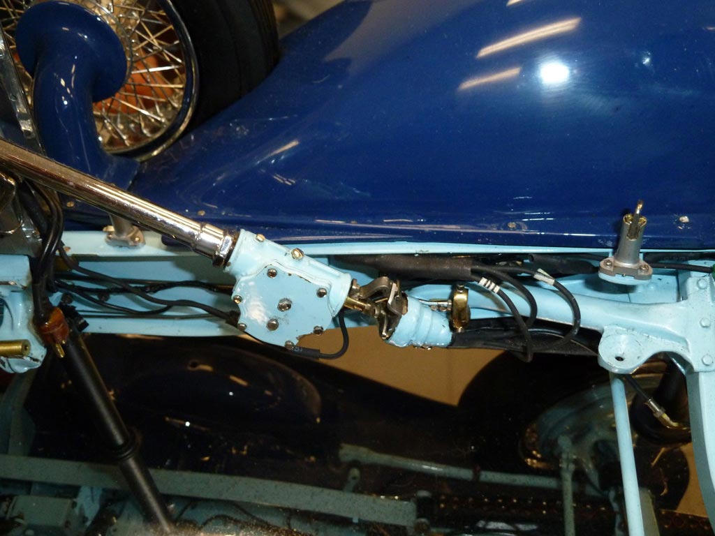
Close-up of the Steering Gearbox
Duesenberg Engine
This display of the Duesenberg at the Craftsmanship Museum was the last chance for the public to view the engine out of the car. These photos show the rear, left side, front and right side.
Duesenberg Engine
Once Lou returned to his home shop in Missouri after this trip, the engine was re-installed in the car, never to be run again. Lou started the engine several times during this day for visitors of the Craftsmanship Museum.
Duesenberg Engine
The extra large distributor was made necessary due to the fact that it still requires 10,000 volts to fire the tiny spark plugs, just like on the real engine.
Duesenberg Engine
The miniature distributor Lou tried first couldn’t contain the spark, so he built one that is hidden behind the firewall when the engine is installed in the car.
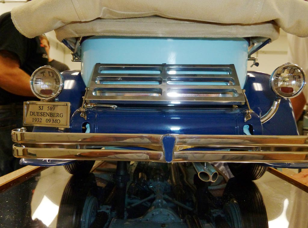
Duesenberg Rear View
The rear view of a true classic. Note the tip of the dual exhaust, and the word “STOP” printed in both tail lights. Congratulations to Lou for the construction of a true masterpiece, and many thanks for letting the Craftsmanship Museum serve as the venue for its final run!
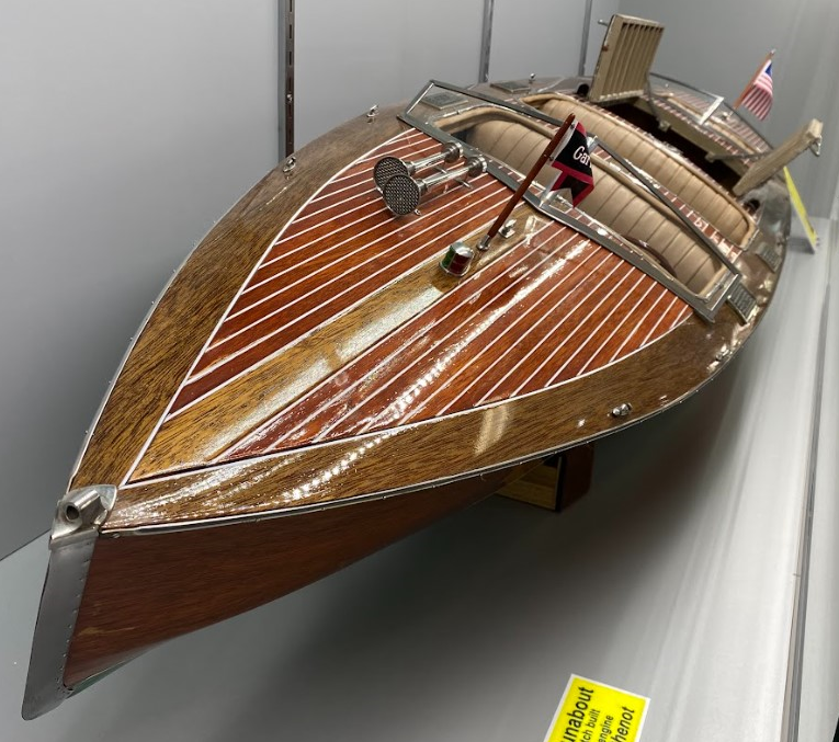
1/6 Scale Gar Wood 33-50 Runabout With Liberty V-12 Engines
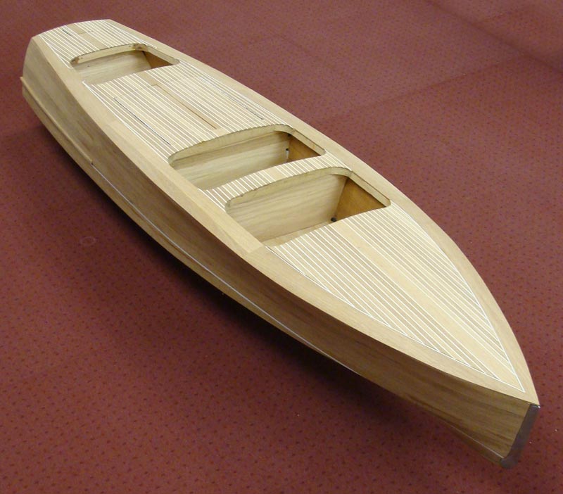
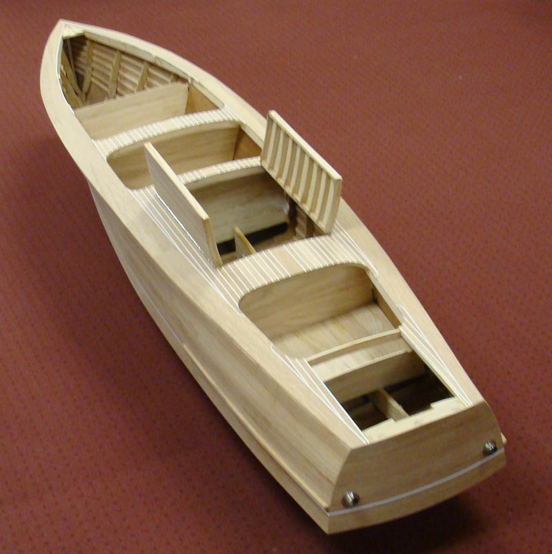
1/6 Scale Gar Wood Hull
Early construction on the Gar Wood hull.
1/6 Scale Gar Wood Hull
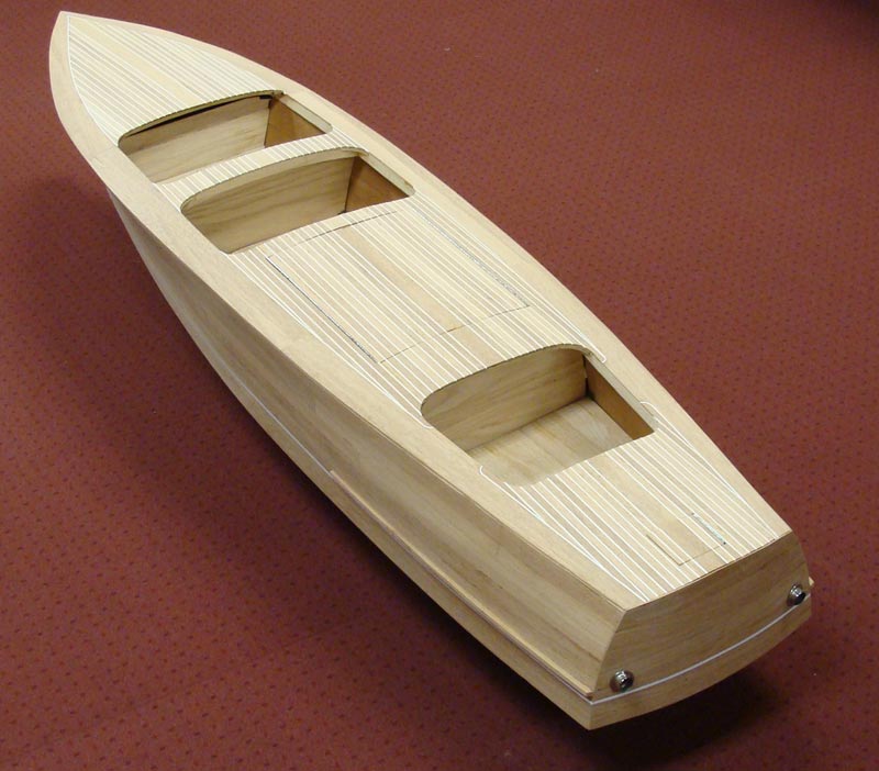
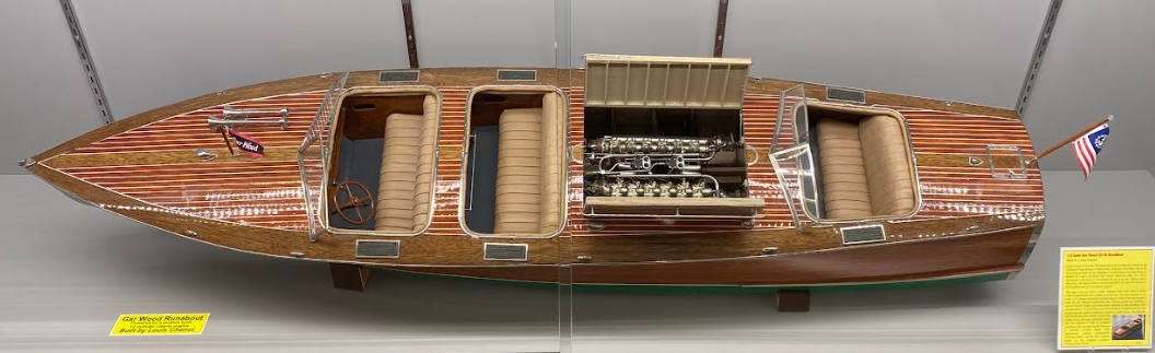
1/6 Scale Gar Wood Runabout
1/6 Scale Gar Wood Runabout
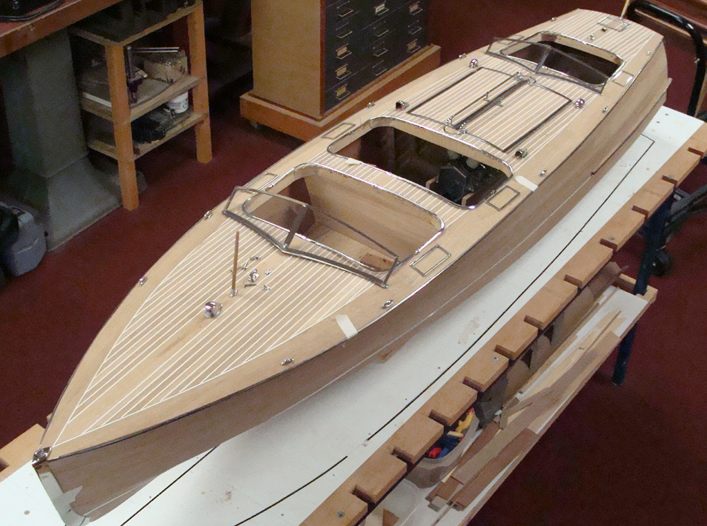
1/6 Scale Gar Wood Runabout
An updated look at the Gar Wood hull, with more improvements.
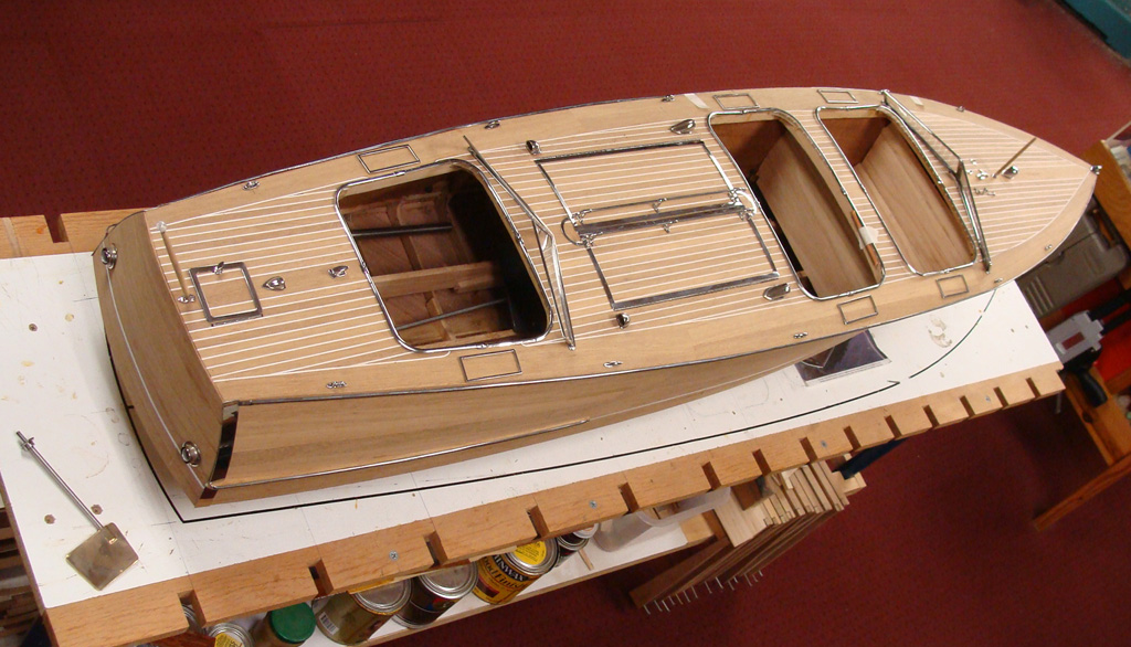
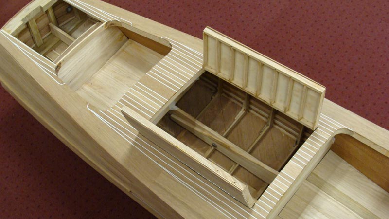
1/6 Scale Gar Wood Runabout
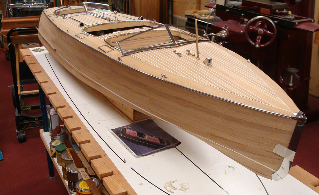
1/6 Scale Gar Wood Runabout
1/6 Scale Liberty Engine Construction
1/6 Scale Liberty Engine Construction
Machining a bevel gear.
1/6 Scale Liberty Engine Construction
Machining a bevel gear.
Liberty Engine Bevel Gears
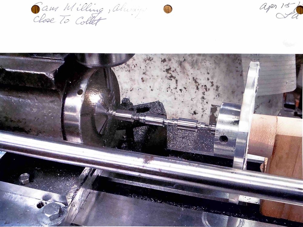
1/6 Scale Liberty Engine Construction
A cam milling operation for the V-12.
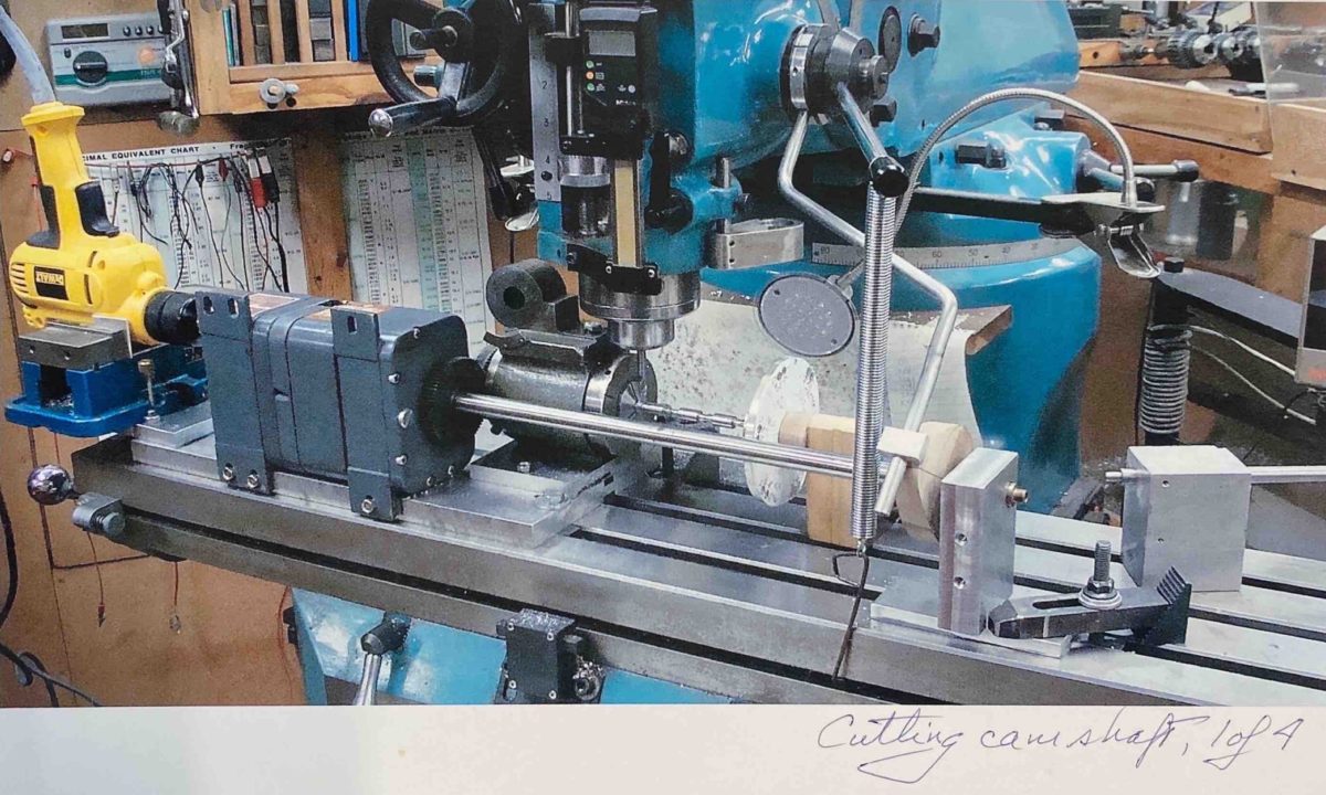
1/6 Scale Liberty Engine Construction
Machining a camshaft.
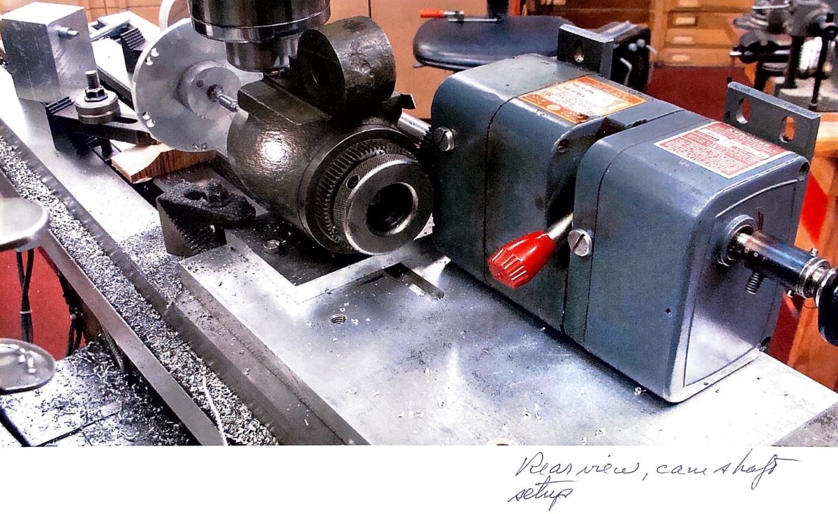
1/6 Scale Liberty Engine Construction
A rear view of the camshaft setup.

1/6 Scale Liberty Engine Construction
Milling flats on valve cages.
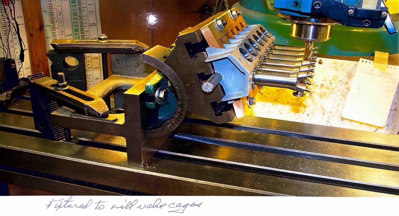
1/6 Scale Liberty Engine Construction
A wider view of the fixture to mill valve cages.
1/6 Scale Liberty Engine Construction
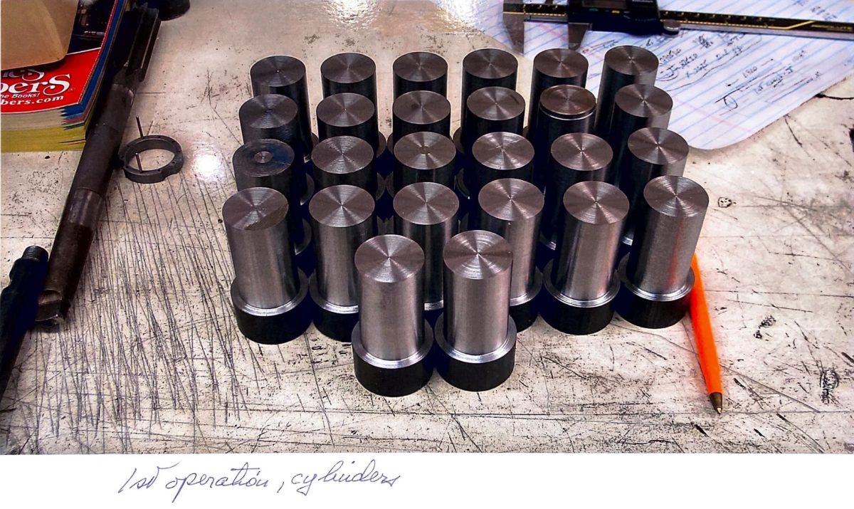
Liberty V-12 cylinders ready for first operation.
1/6 Scale Liberty Engine Construction
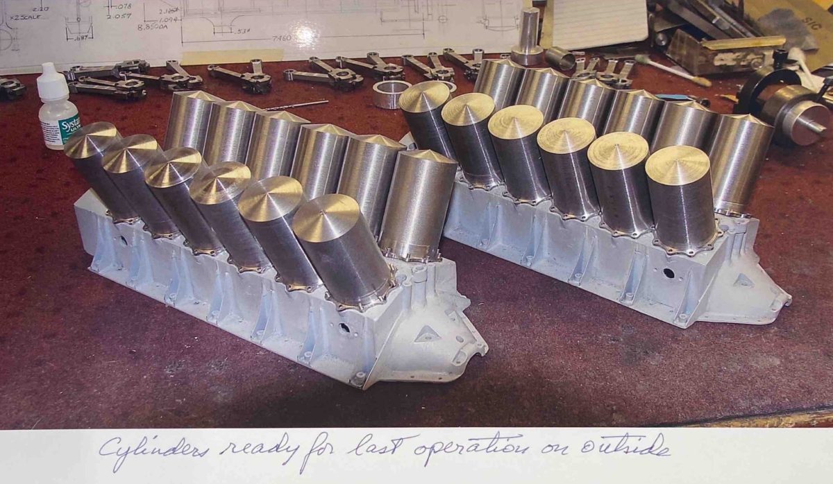
The cylinders are ready for the last operation on the outside.

1/6 Scale Liberty Engine Construction
Liberty V-12 cylinders after the second operation.
1/6 Scale Liberty Engine Construction
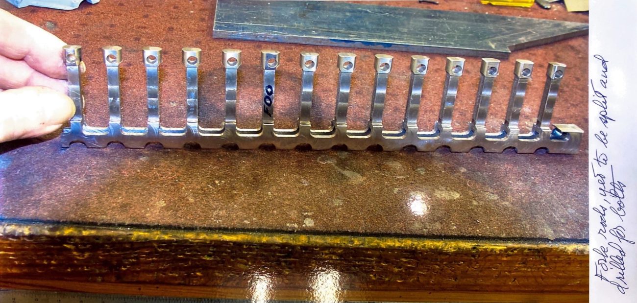
Fork rods yet to be split and drilled for bolts.
1/6 Scale Liberty Engine Construction
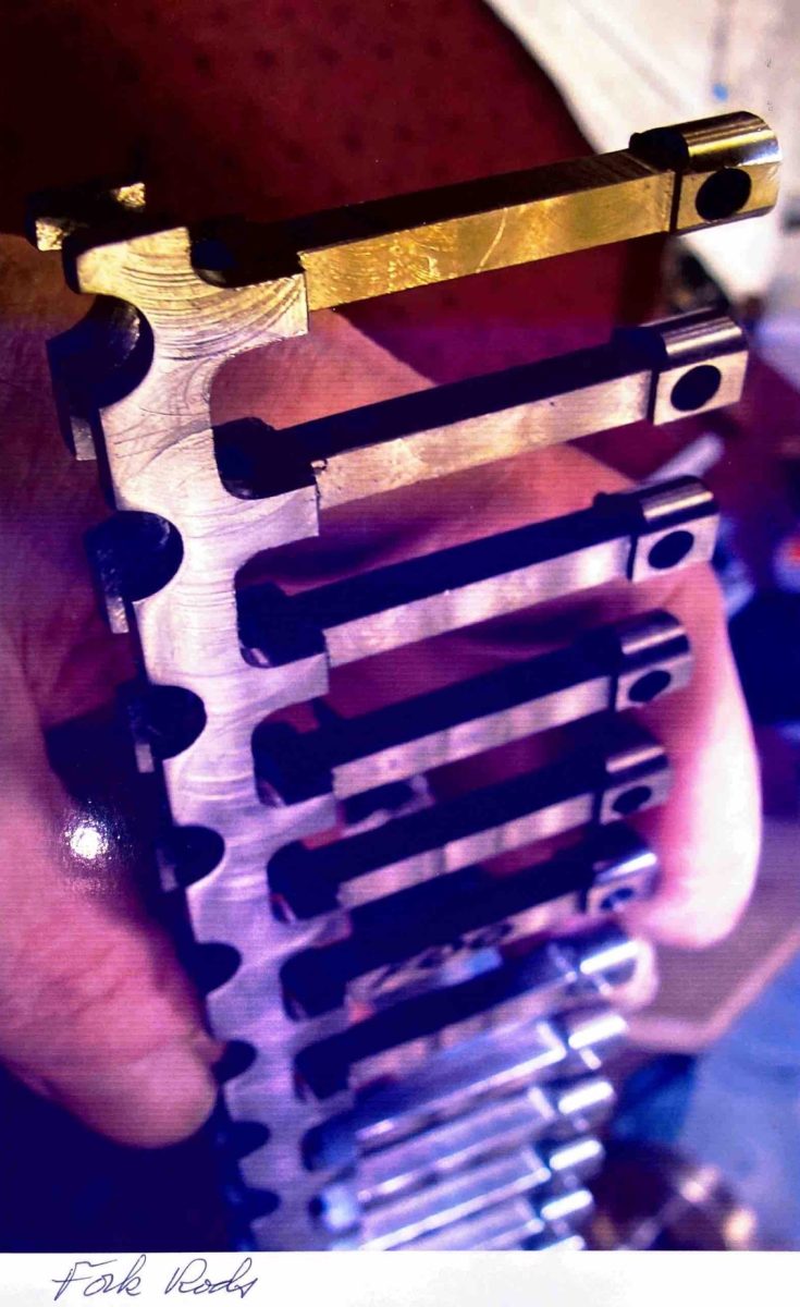
A closer look at the fork rods.
1/6 Scale Liberty Engine Construction
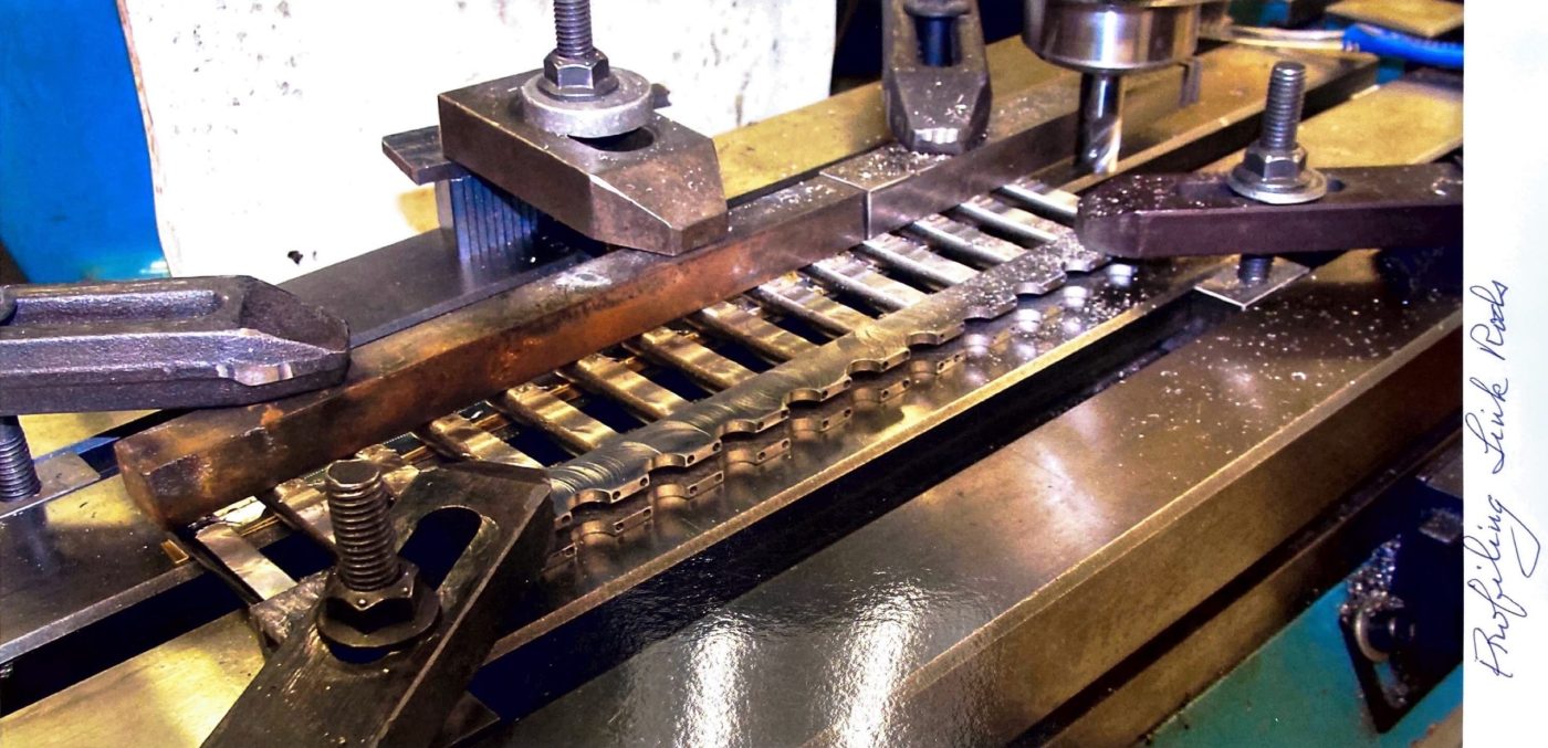
Profiling link rods.
1/6 Scale Liberty Engine Construction
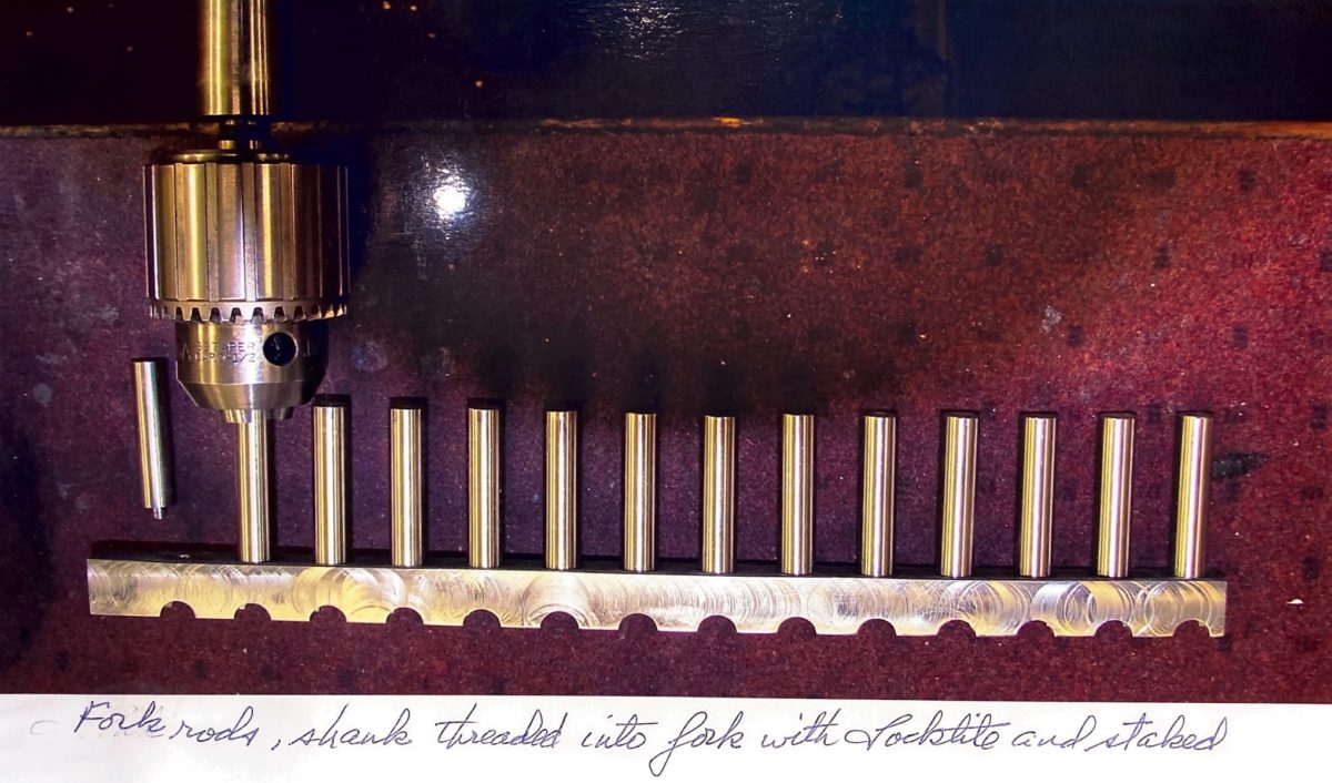
More work on the fork rods. The shank is threaded into fork with locktite and staked.

1/6 Scale Liberty Engine Construction
Drilling oil holes for the V-12 Liberty.
1/6 Scale Liberty Engine Construction
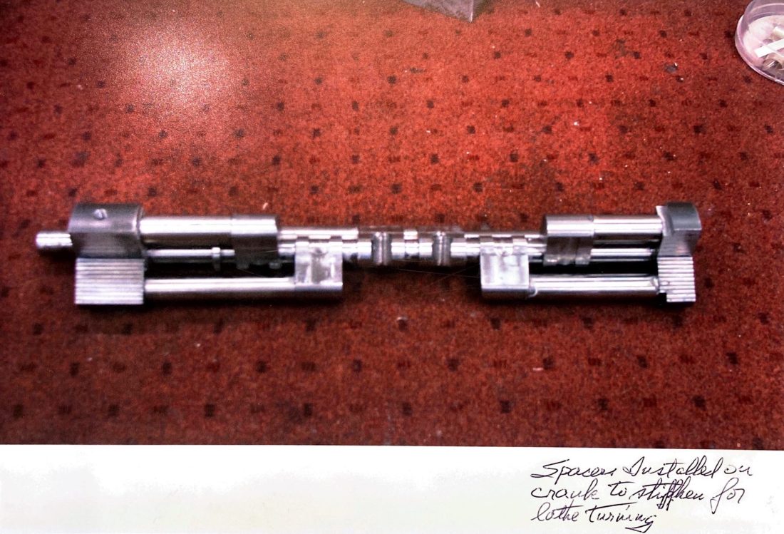
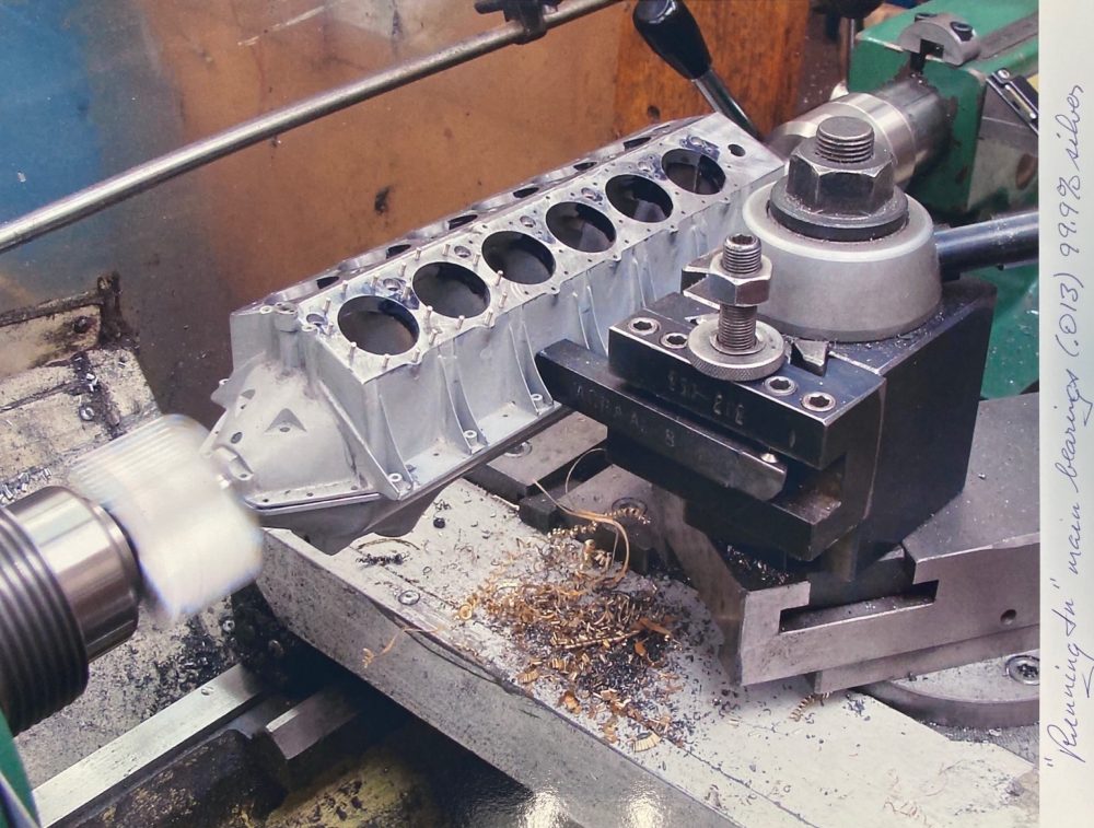
Spacers installed on crank to stiffen for lathe turning.
1/6 Scale Liberty Engine Construction
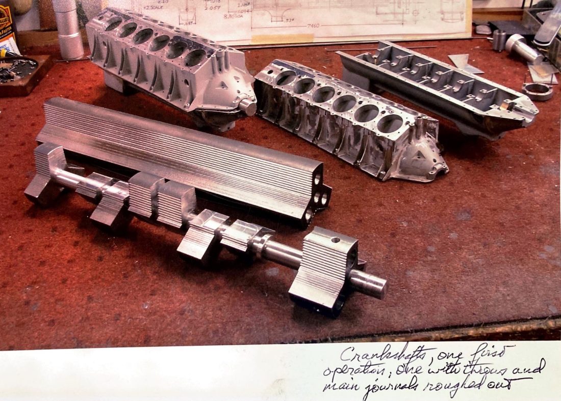
Two crankshafts at different stages of machining. The one in front has the throws and main journals roughed out.
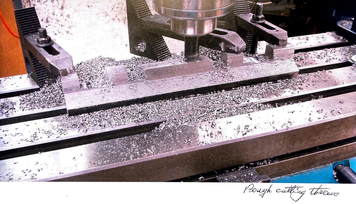
1/6 Scale Liberty Engine Construction
Rough cutting throws in the crankshaft.
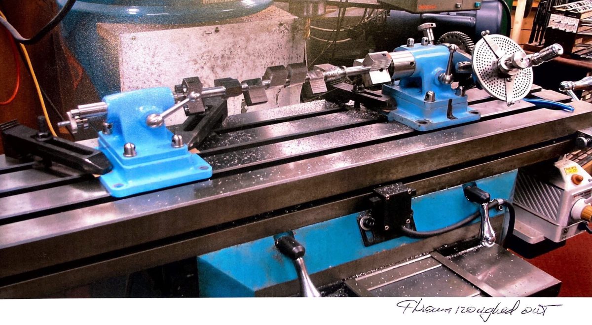
1/6 Scale Liberty Engine Construction
The same crankshaft with throws roughed out.
1/6 Scale Liberty Engine Construction
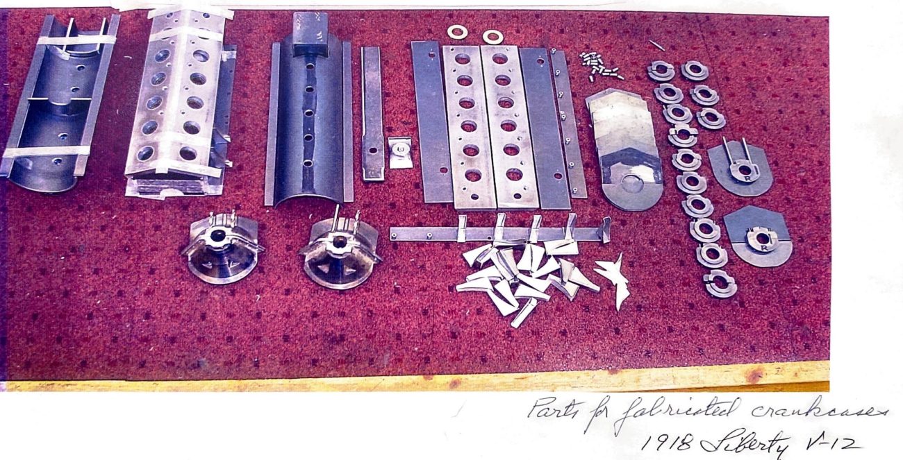
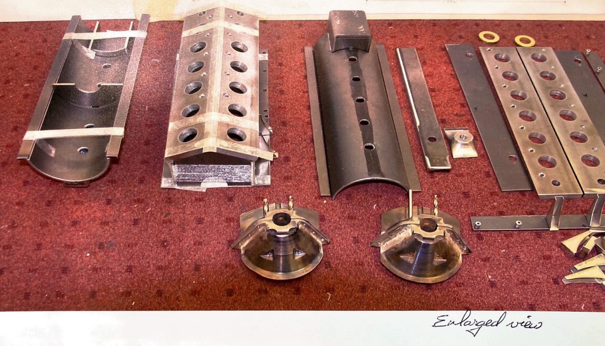
1/6 Scale Liberty Engine Construction
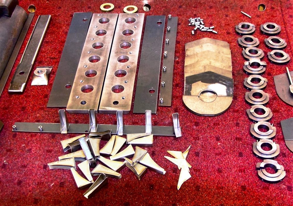
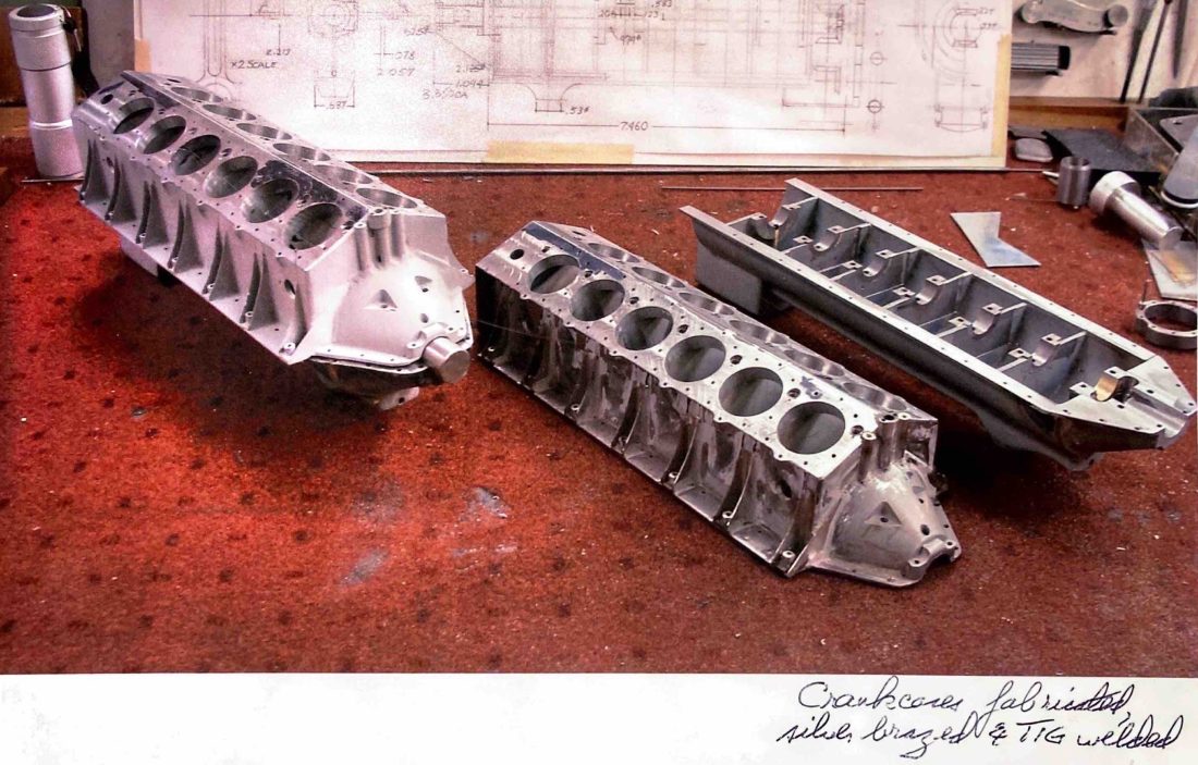
Parts for fabricated crankcases for the Liberty V-12.
1/6 Scale Liberty Engine Construction
1/6 Scale Liberty Engine Construction
1/6 Scale Liberty Engine Construction
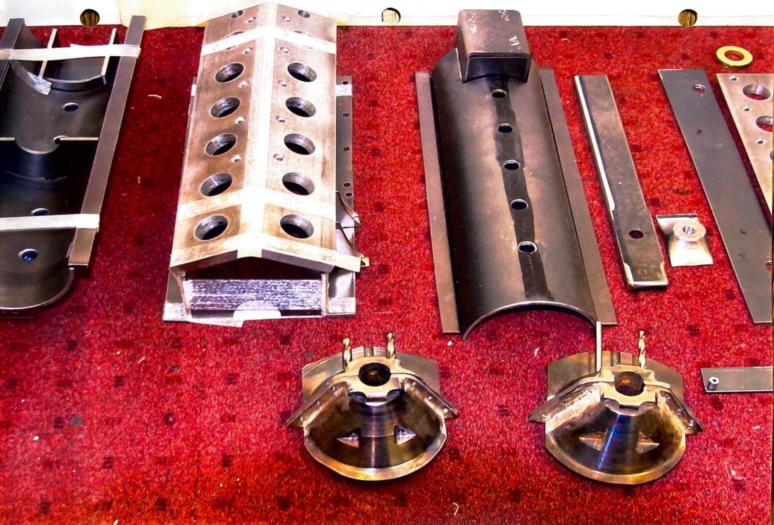
The Liberty V-12 crankcases coming along.
1/6 Scale Liberty Engine Construction
1/6 Scale Liberty Engine Construction
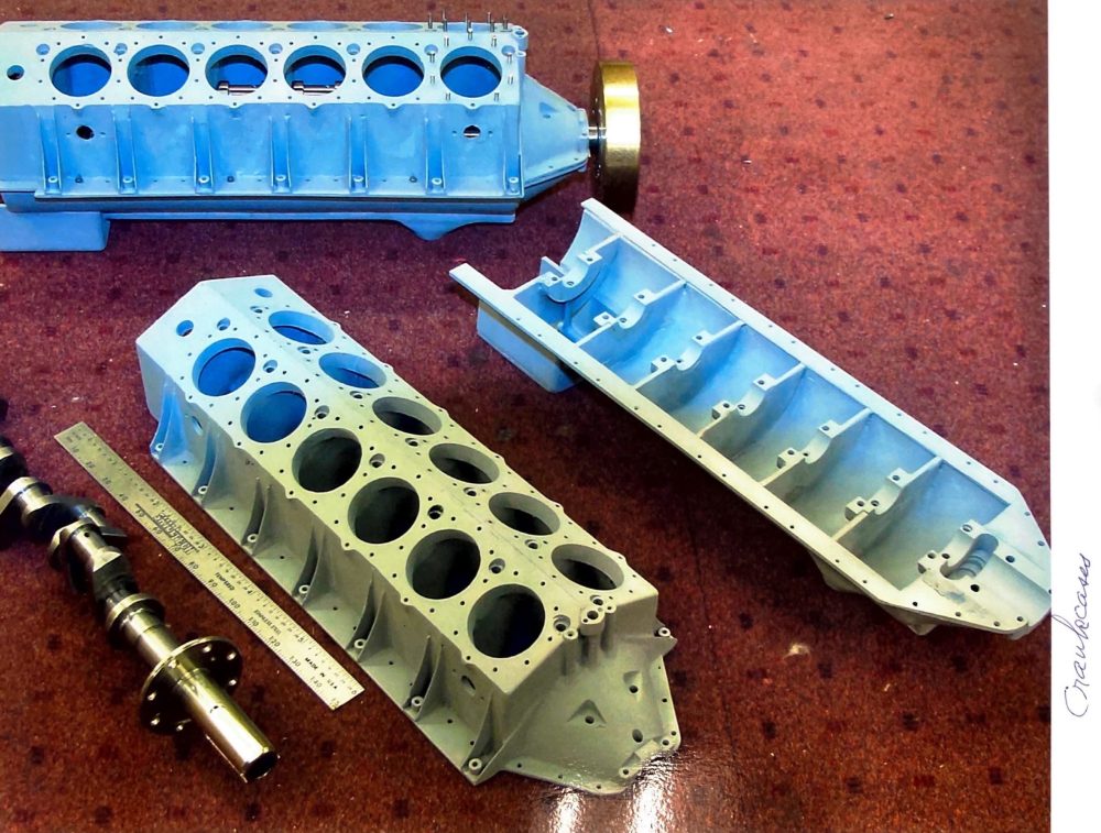
Liberty V-12 crankcases fabricated, silver brazed and TIG welded.
1/6 Scale Liberty Engine Construction
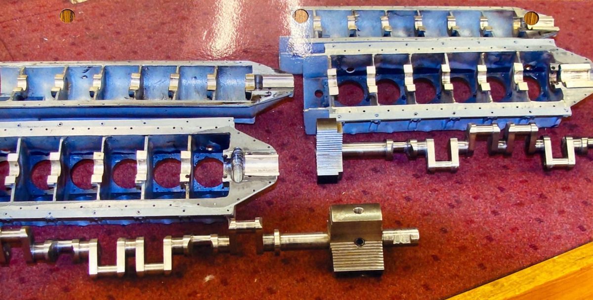
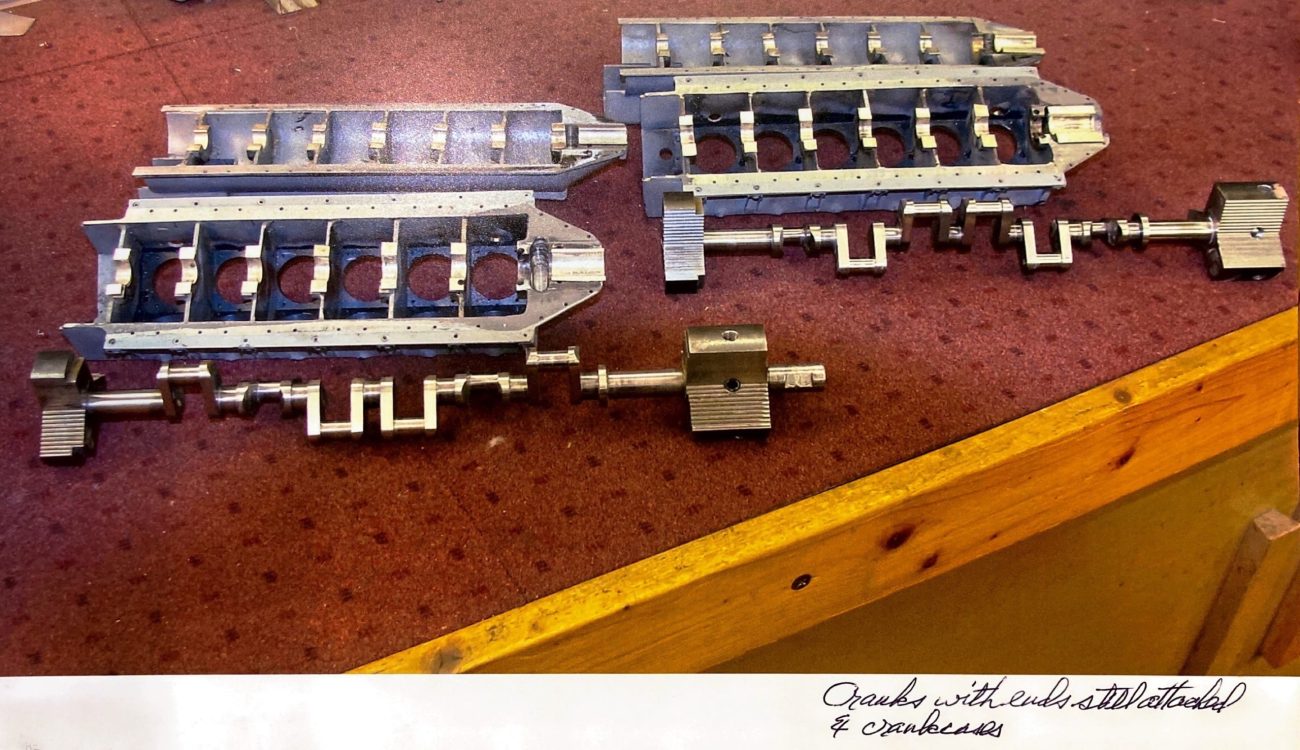
Crankshafts and crankcases for the Liberty V-12.
1/6 Scale Liberty Engine Construction
1/6 Scale Liberty Engine Construction
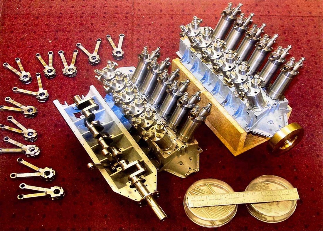
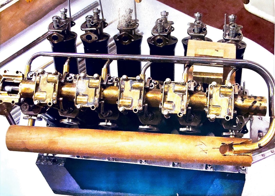
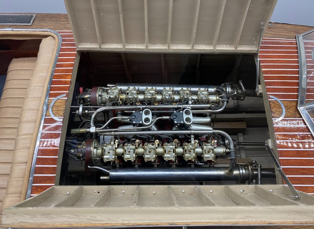
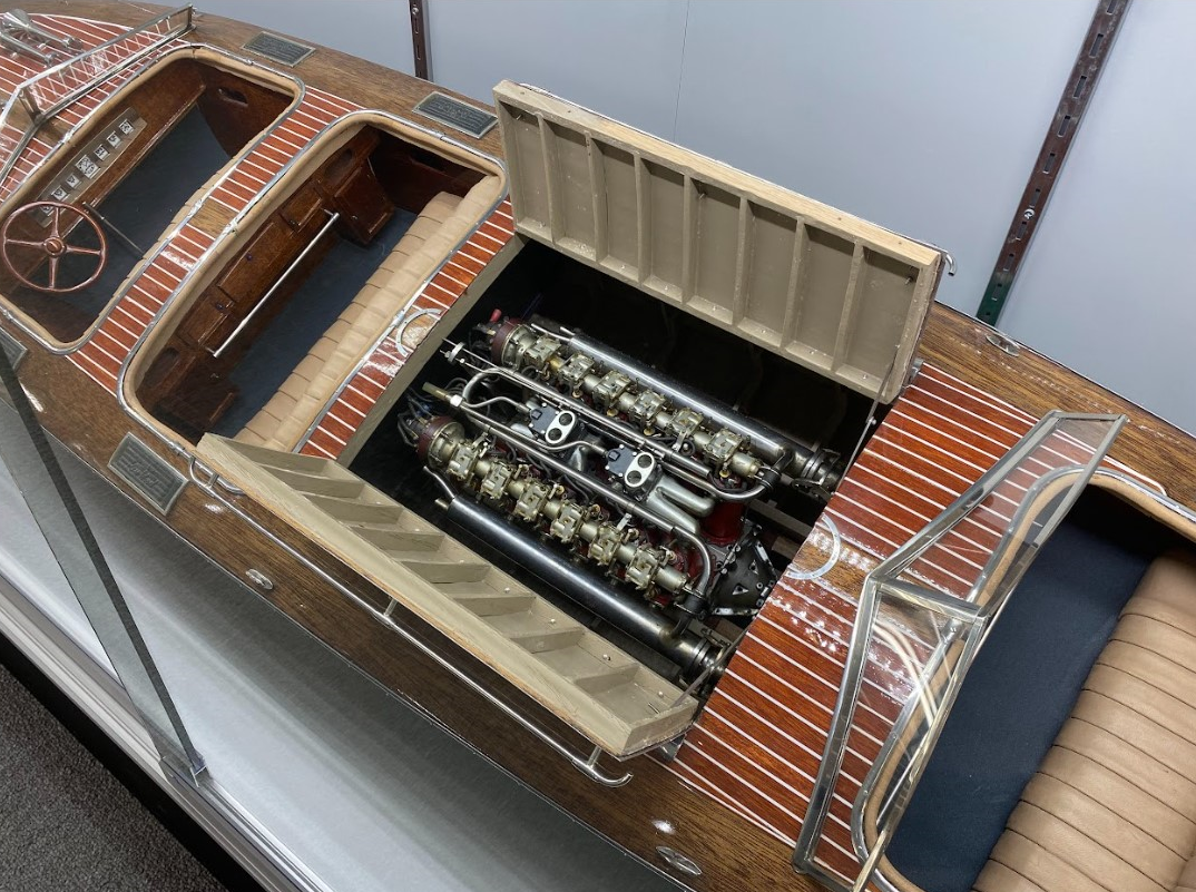
1/6 Scale Liberty V-12 Engines
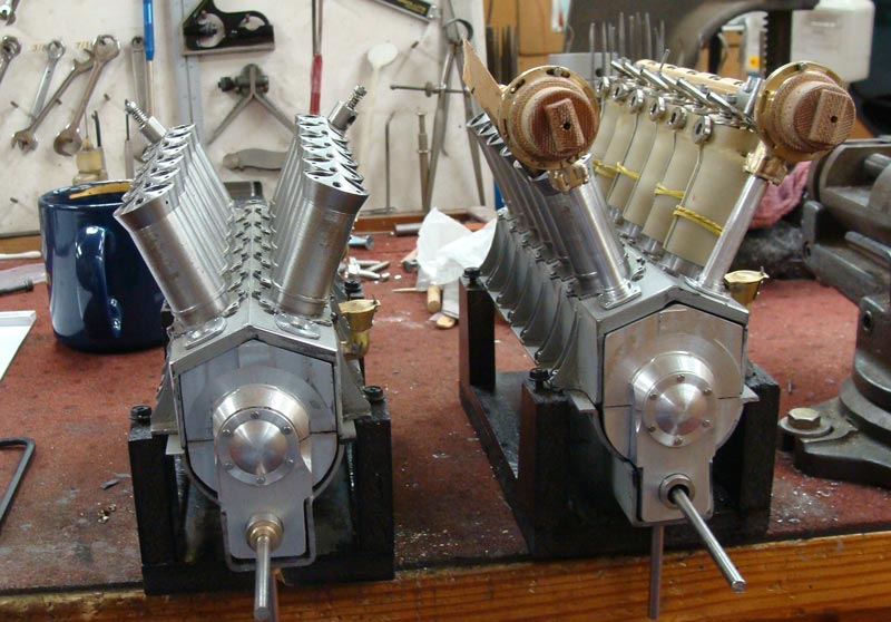
1/6 Scale Liberty V-12 Engines
Two Liberty V-12 engines under construction.
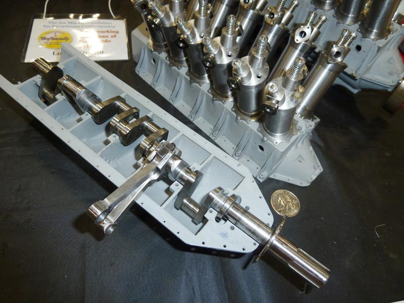
Liberty V-12 Engines
Early progress on the Liberty V-12 engine, as shown at the NAMES Expo in Southgate, MI.
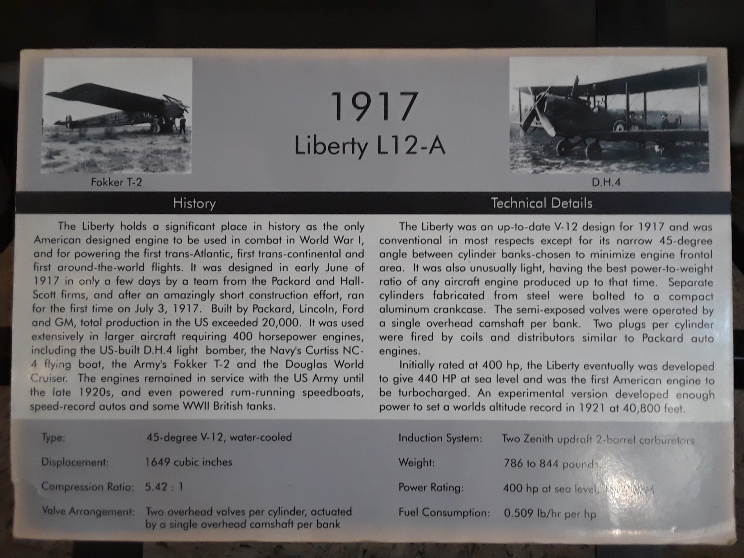
Liberty V-12 Engine Placard
Some information on the history of the Liberty aircraft engine.
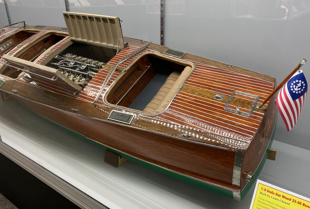
1/6 Scale Gar Wood Runabout
Lou’s finished 1/6 scale Gar Wood 33-50 Runabout with Liberty V-12 engine is now on permanent display at the Miniature Engineering Craftsmanship Museum.
1/6 Scale Gar Wood Runabout
1/6 Scale Gar Wood Runabout
1/6 Scale Gar Wood Runabout
1/6 Scale Gar Wood Runabout
1/6 Scale 1895 American LaFrance Fire Engine
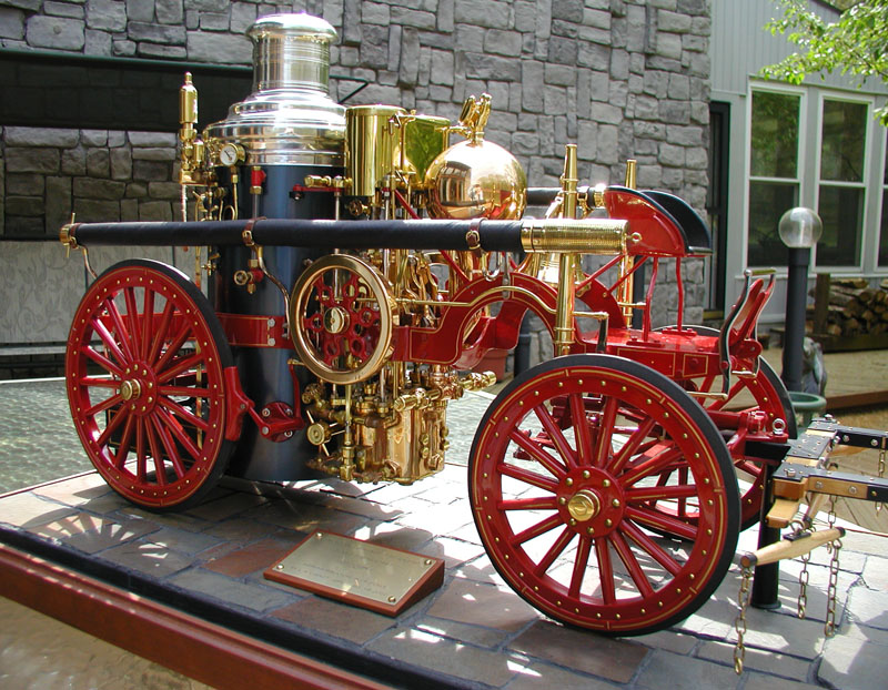
1895 American LaFrance Fire Engine
This fire engine was built over a 25-year period, and finished in Lou’s first year of retirement. It probably required 4,000-5,000 hours. Initially, a set of plans from Cole’s was purchased, along with engine and pump castings. Charlie Cole’s drawings were not very well scaled, but are a facsimile of an American LaFrance 1895 pumper, which he points out in his description.
1895 American LaFrance Fire Engine
However, books on such machines, photographs, and the fact that the original exists in the company museum allowed it to be built more accurately. Also, the castings at that time were not very good. Porosity caused most of the connecting engine links to be scrapped.
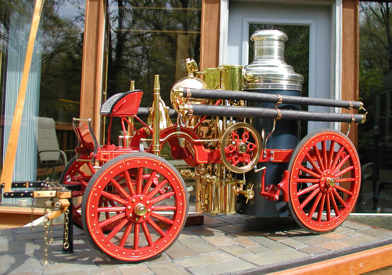
1895 American LaFrance Fire Engine
Lou decided to build with original materials, so that the wheels are cherry wood (constructed as would a wheelwright), and the frames are steel with working leaf springs. The engine/pump was run on air for several hours, and the boiler was hydrostatically tested to 100 psi. It has not been run after assembly.
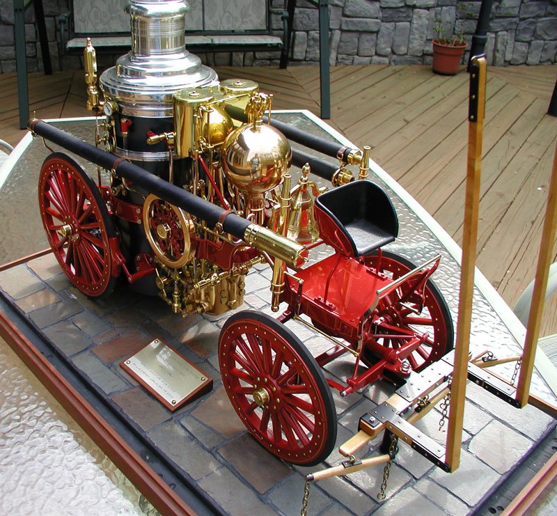
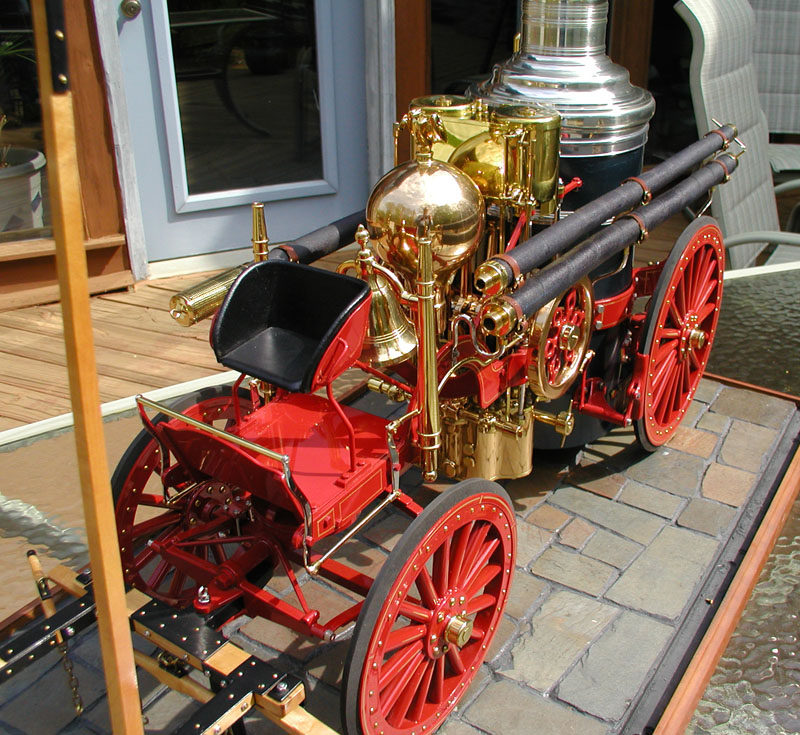
1895 American LaFrance Fire Engine
The model is very difficult to clean, and so resides in a glass case. It’s also heavy—at about 60 lbs.—and has become difficult to show. Incidentally, it is about 30″ long. The fire engine model was recently sold at auction at the Cabin Fever model engineering show in York, PA.
1/6 Scale Bentley Rotary Aircraft Engine
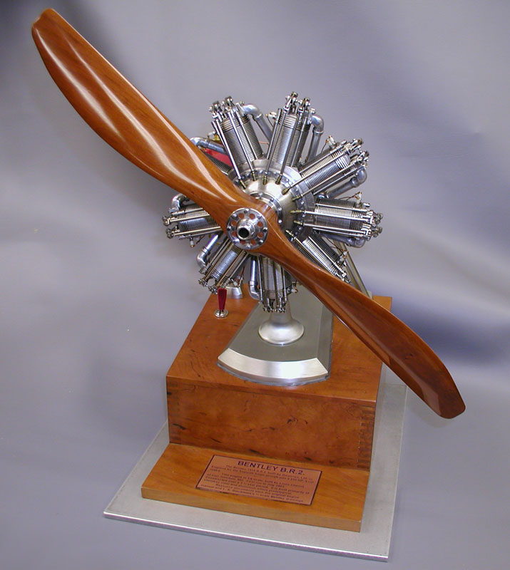
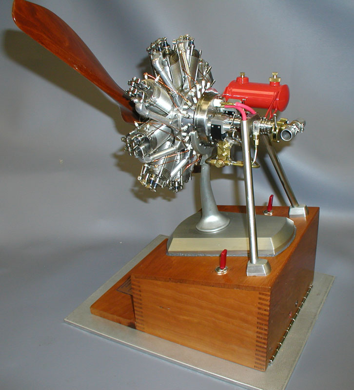
Bentley Rotary Aircraft Engine
W.O. Bentley is well known for his racing automobiles, but he was a very good engineer in other efforts, too—such as this 1918 9-cylinder rotary engine.
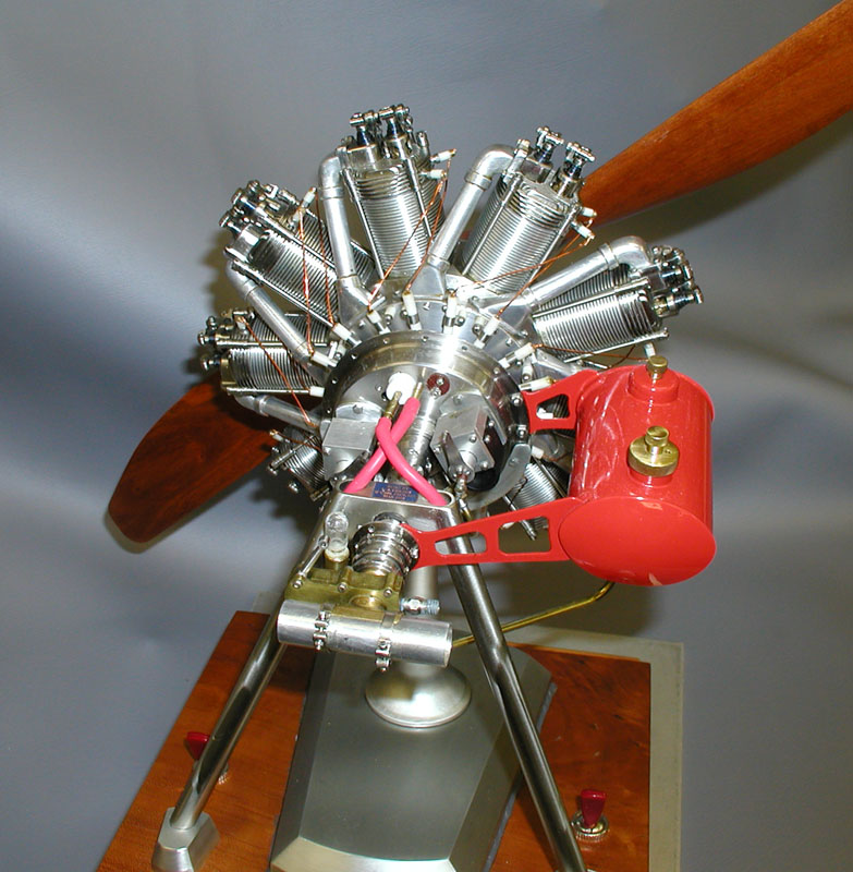
Bentley Rotary Aircraft Engine
The crankshaft is bolted to the aircraft frame, a Sopwith “Snipe” of which approximately 5000 were built. Consequently, cylinders rotate with the prop. It seems strange now, but it cooled the engine.
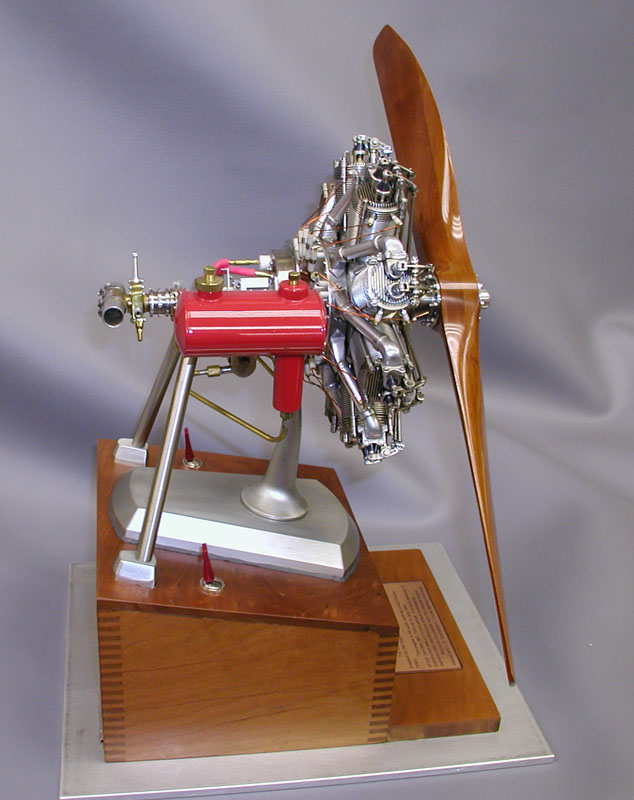
Bentley Rotary Aircraft Engine
The design was very modern for its time, and produced 240-HP. A model in 1/6 scale seemed appropriate to Lou. Even so, it swings an 18-inch propeller.
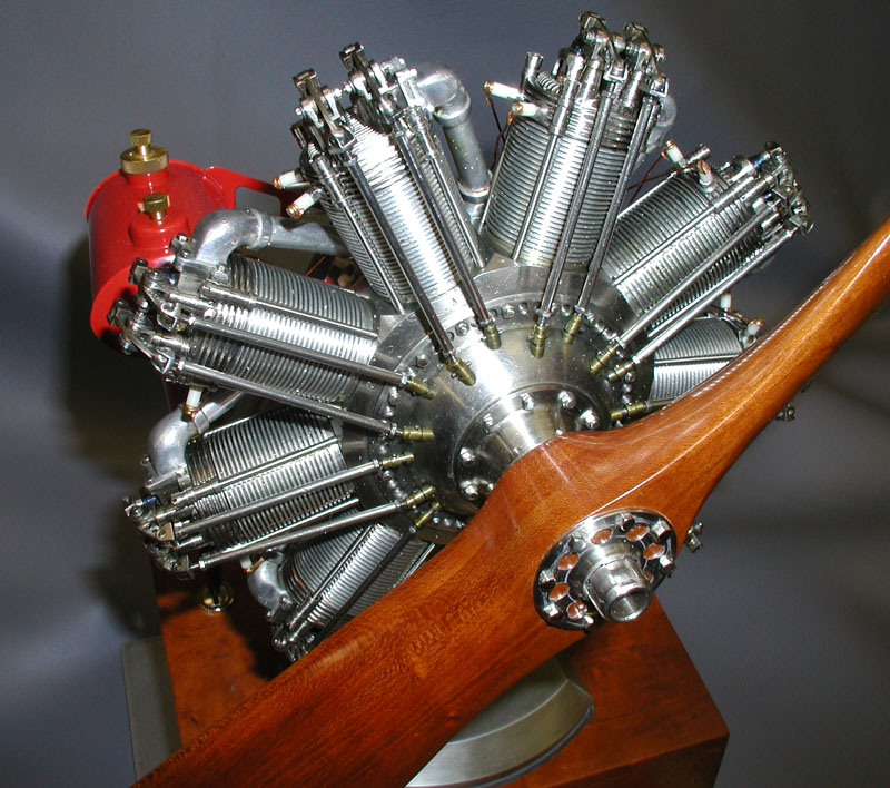
Bentley Rotary Aircraft Engine
Another 4000 hours went into this project. Lou had to learn more about investment casting to make the intake elbows.

Bentley Rotary Aircraft Engine
The prototype crankcase pieces were steel, but being concerned with rust, Lou chose to use stainless steel everywhere except for the aluminum finned barrels, which are authentic.
Bentley Rotary Aircraft Engine
This model is also now on permanent display at the Miniature Engineering Craftsmanship Museum in Carlsbad, CA.