Below you can view more photos of Ken’s airplanes and other projects, with some of the steps for building them. Click on images to enlarge.
1/15 Scale Sopwith Camel
Sopwith Camel
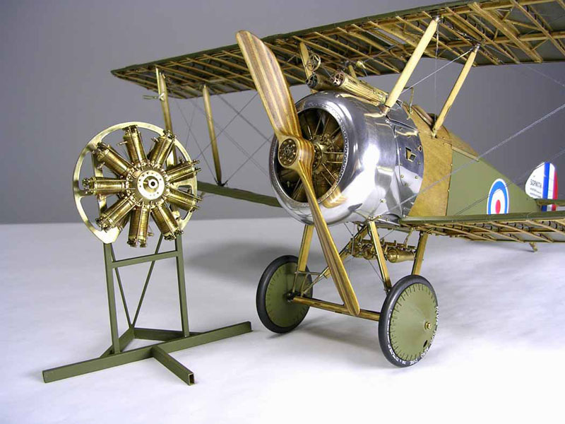
Ken’s 1/15 scale Sopwith Camel includes a second engine on a stand. Note that this side is covered and painted.
Sopwith Camel
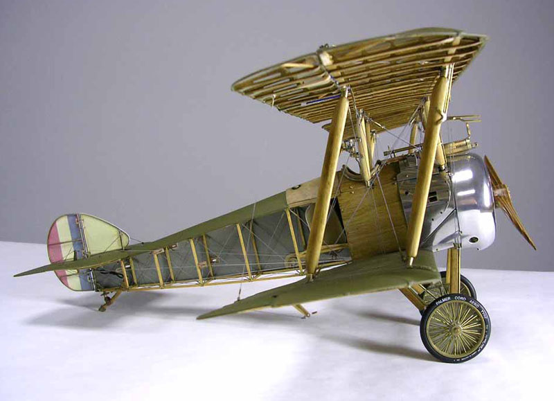
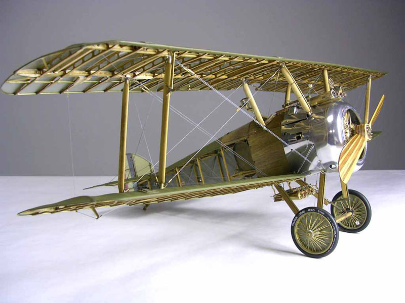
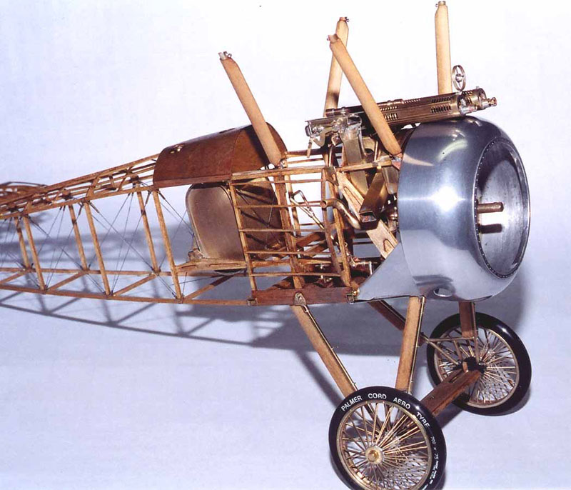
A right side view of the Sopwith Camel. This side is left as a cutaway so the interior structure can be seen.
Sopwith Camel
Another view of the cutaway side.
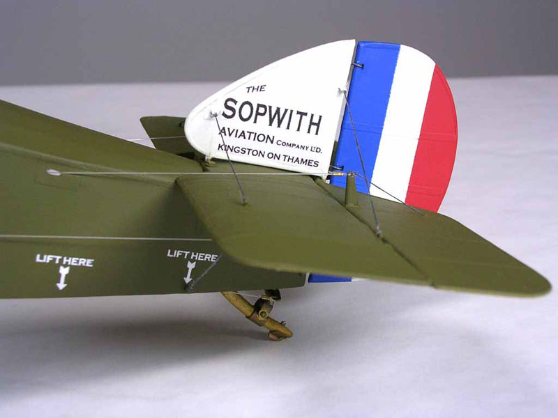
Sopwith Camel Tail
A detail view of the graphics on the tail.
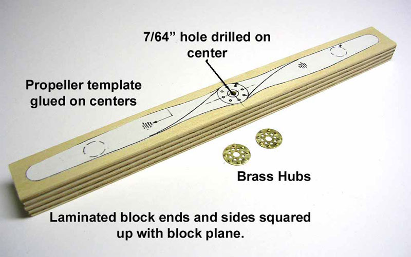
Propeller Construction
The making of a laminated propeller, starting with the laminated block in this photo.
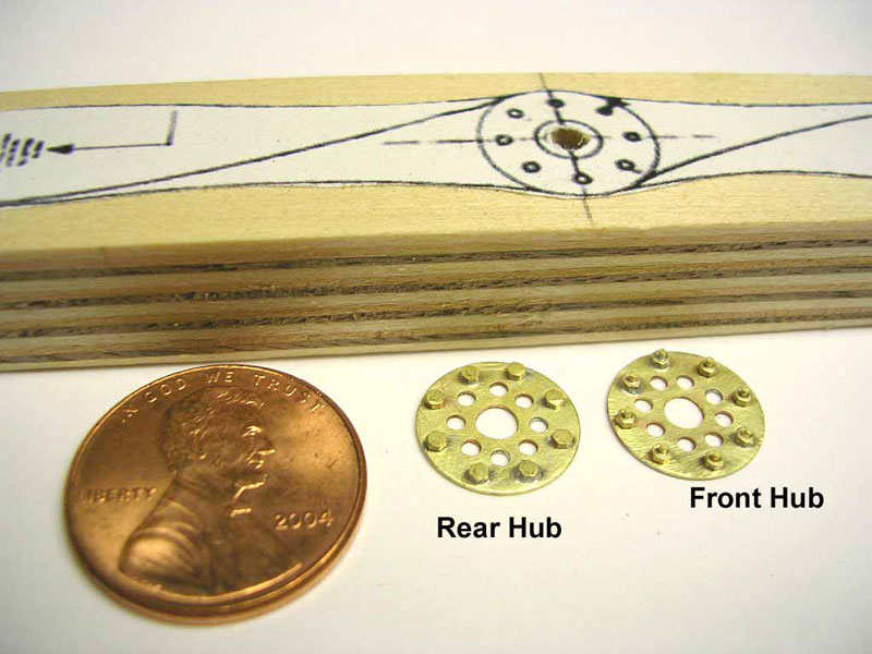
Propeller Construction
A penny offers scale reference.
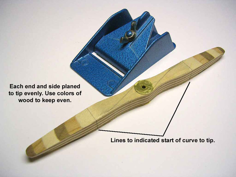
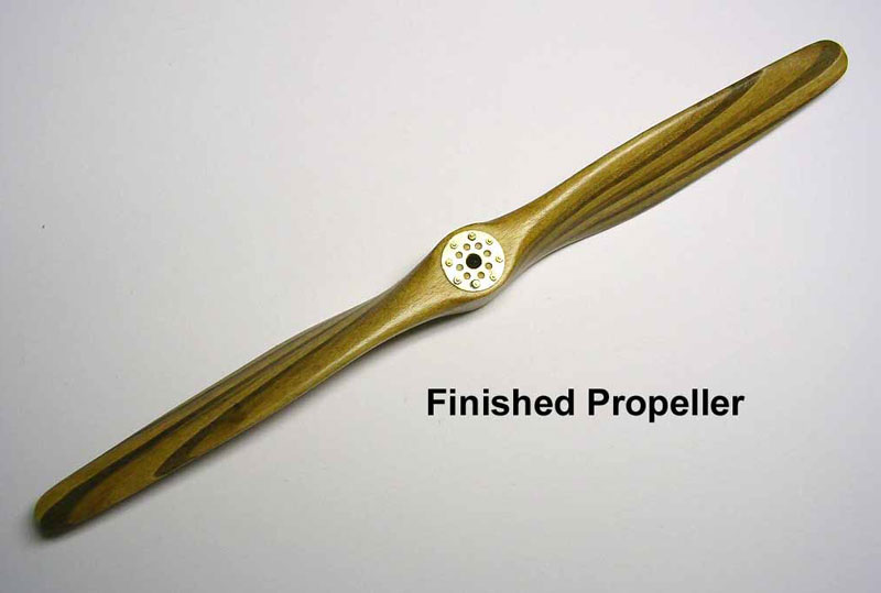
Propeller Construction
The shaped form coming along.
Propeller Construction
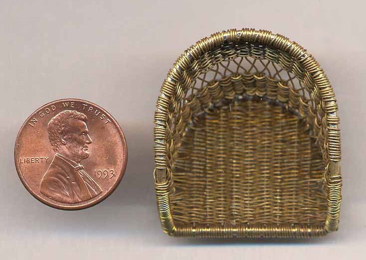
Sopwith Camel Seat
The wicker seat is woven, not with wicker, but rather with fine annealed wire. The effect is absolutely authentic.
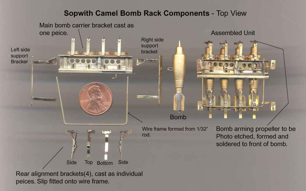
Sopwith Camel Bomb Rack
The components of the bomb rack.
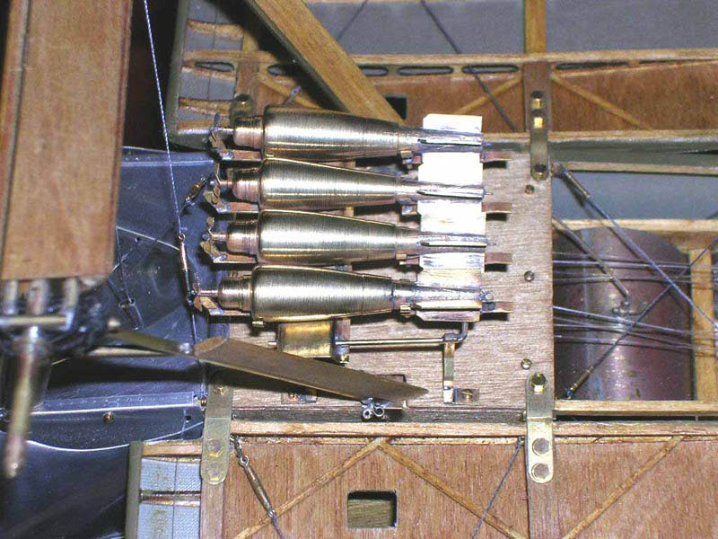
Sopwith Camel Bomb Rack
The finished bomb rack installation.
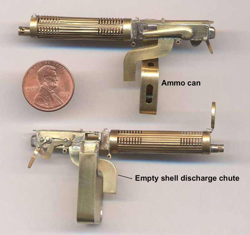
Vickers Machine Guns
The detailed Vickers machine guns for the Sopwith Camel are shown here.
Sopwith Camel With Machine Guns
This photo shows the machine guns mounted on the partially complete Sopwith fuselage.
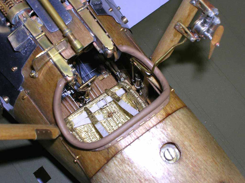
Sopwith Camel Cockpit
This view shows the cockpit from above, revealing the “wicker” seat in place with seatbelts. In the upper right corner of this photo you can see the propeller for the wind-driven fuel pump.
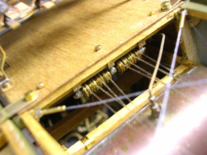
Sopwith Cockpit Control Pulleys
Cables from the cockpit controls run through tiny pulleys. Yes, the controls actually move the wing surfaces.
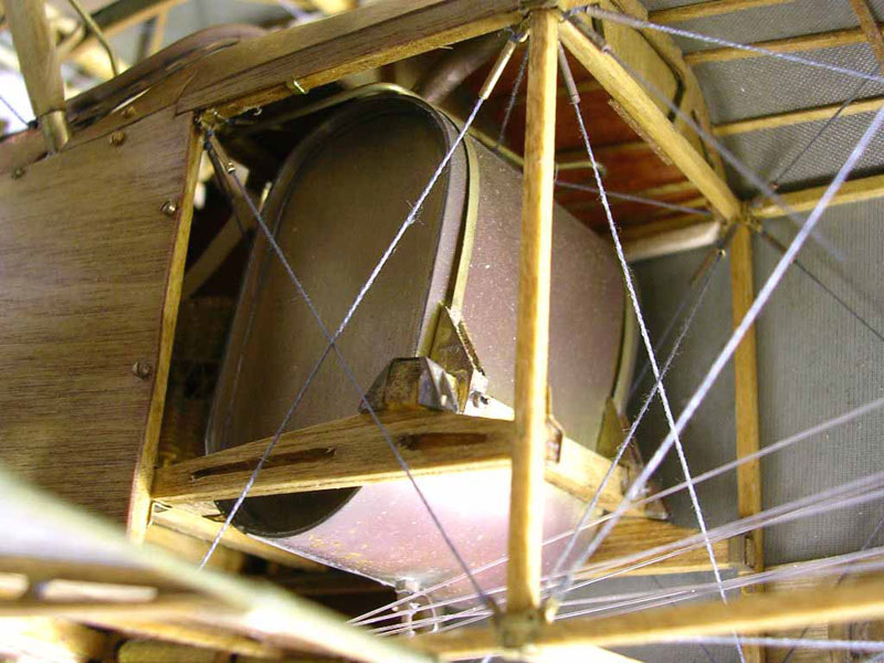
Sopwith Camel Gas Tank
This photo from below the cockpit shows the gas tank.
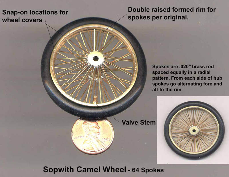
Sopwith Camel Wheels
This photo shows the fine detail in the spokes of the wire wheels. It seems almost a shame to cover all that fine work with the wheel covers shown in the next photo.
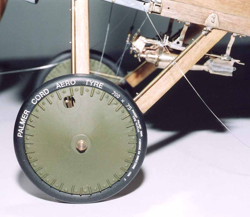
Sopwith Camel Wheels
Here you can see the wire wheels with their wheel covers. However, the other side of the far wheel was left uncovered so that the detail could be seen.
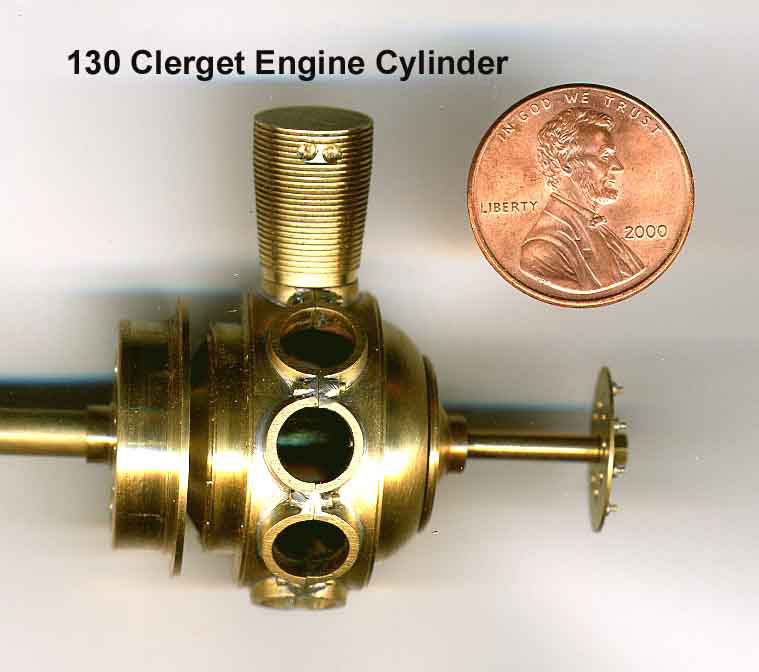
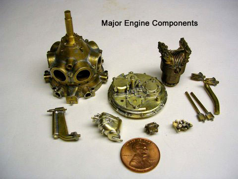
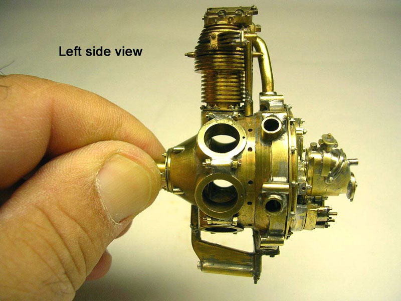
Clerget 130-HP Engine
These photos show details of the 130-HP 9-cylinder radial Clerget engine that powered the Sopwith.
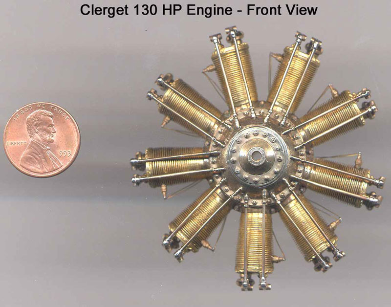
Clerget 130-HP Engine
Note the penny for scale reference.
Clerget 130-HP Engine
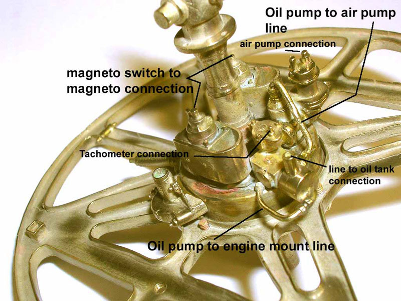
This photo shows some of the engine’s peripheral components.
Bell H-13D Souix M.A.S.H. Helicopter
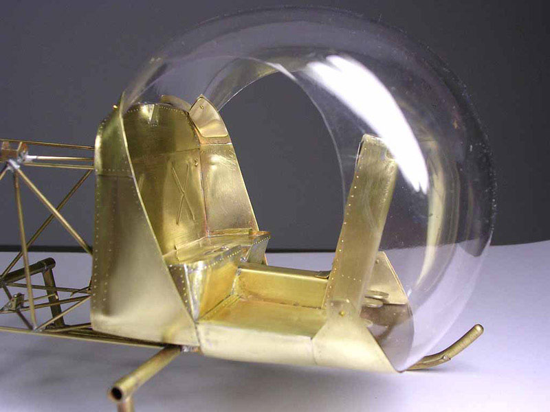
Bell H-13D Cockpit
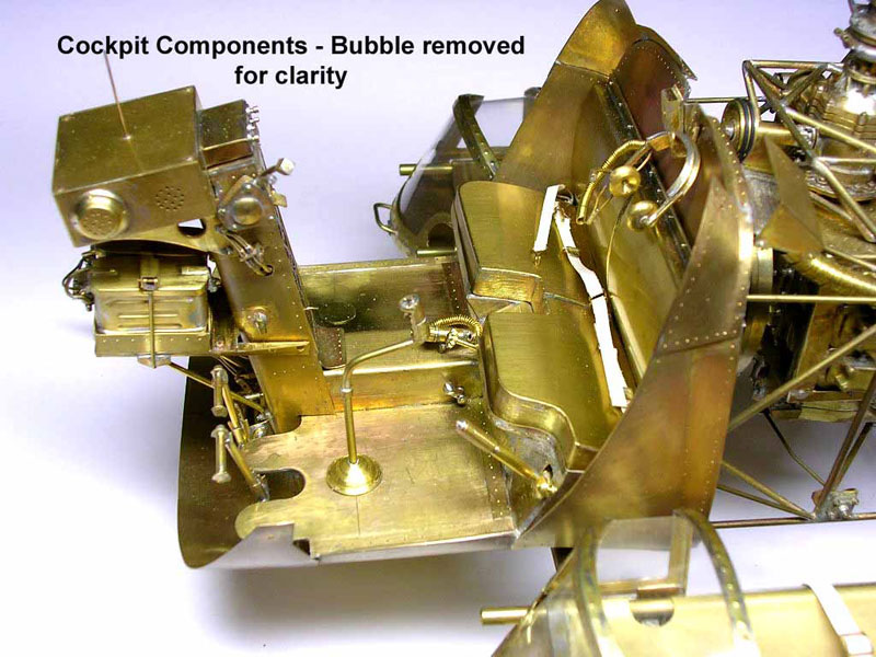
Cockpit details before the bubble canopy was installed.

Franklin Engine
The Franklin engine, transmission, and swash plate for the Bell helicopter.
Franklin Engine
The transmission is separated in this photo.
Franklin Engine
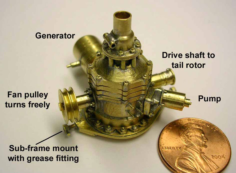
The complete engine/transmission assembly.
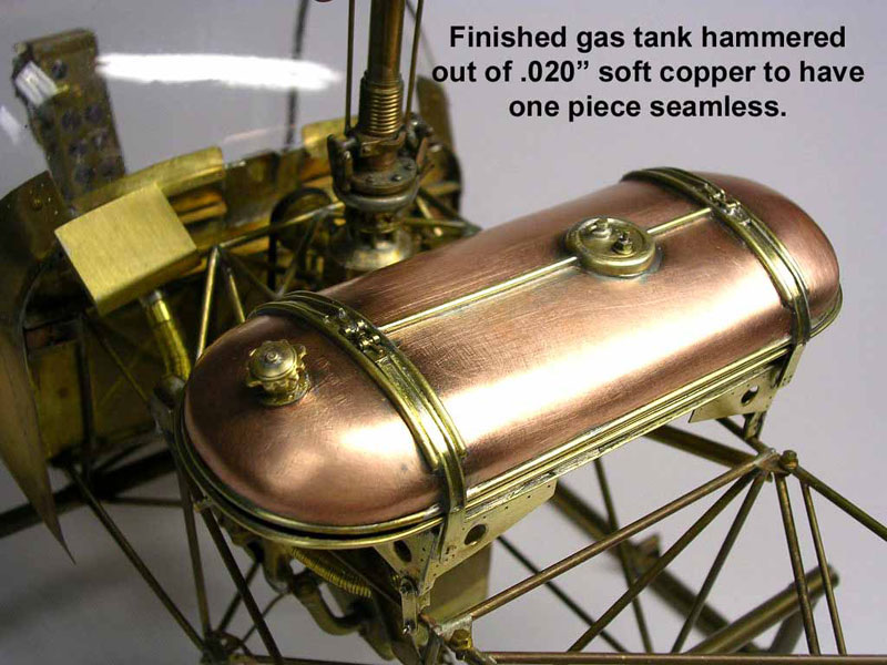
Bell H-13D Gas Tank
The deep curves of the gas tank required the use of softer copper to form its shape. This is another example of Gretchen’s handiwork in miniature metalsmithing.
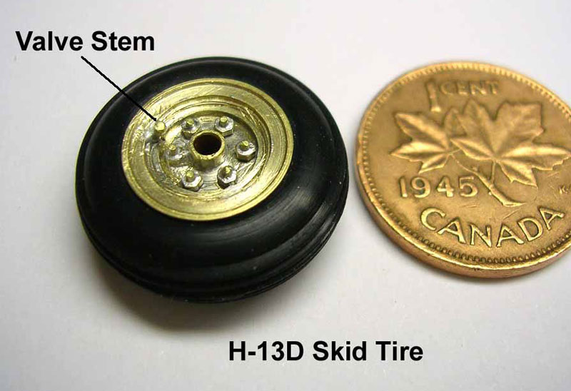
Bell H-13D Wheels
The wheel and tire assembly, complete with lug nuts and valve stem.
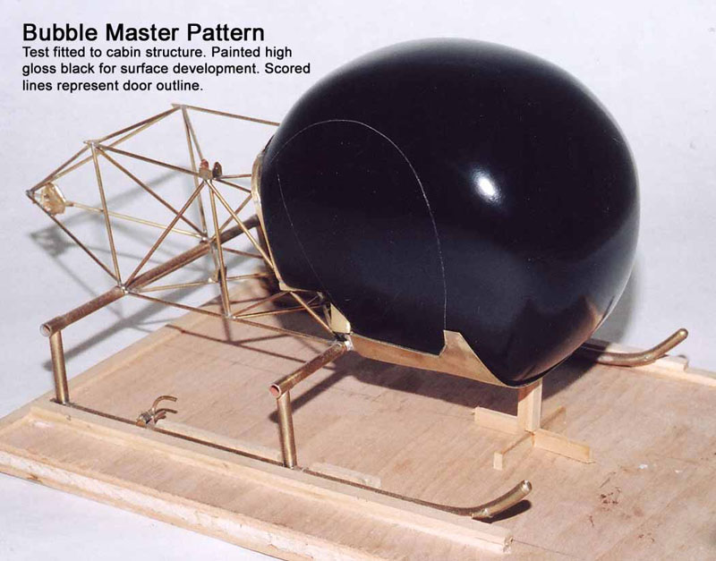
Bell H-13D Bubble Canopy
Making the bubble canopy. First, the shape is carved and painted gloss black so any imperfections show up, and can be corrected.
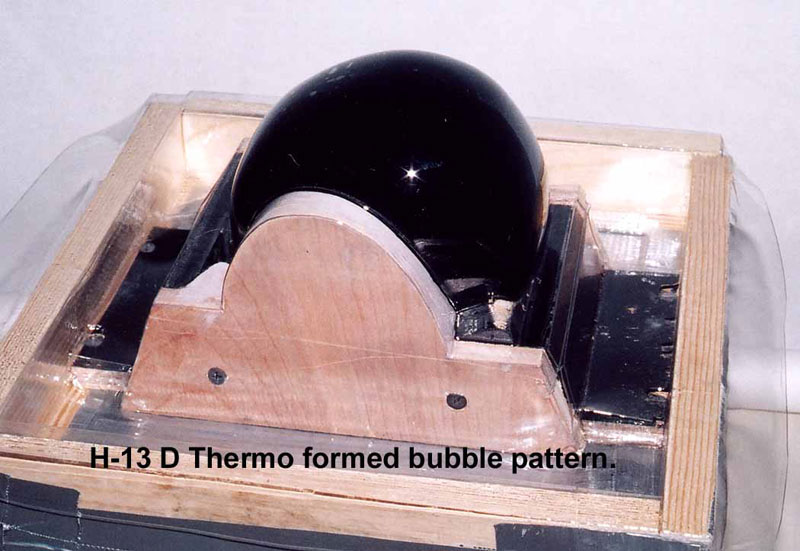
Bell H-13D Bubble Canopy
Then, a vacuum mold is made, and the material is heated and drawn over the form.
Bell H-13D Bubble Canopy
Finally, the edges are trimmed, and the finished canopy is test fitted to the model.
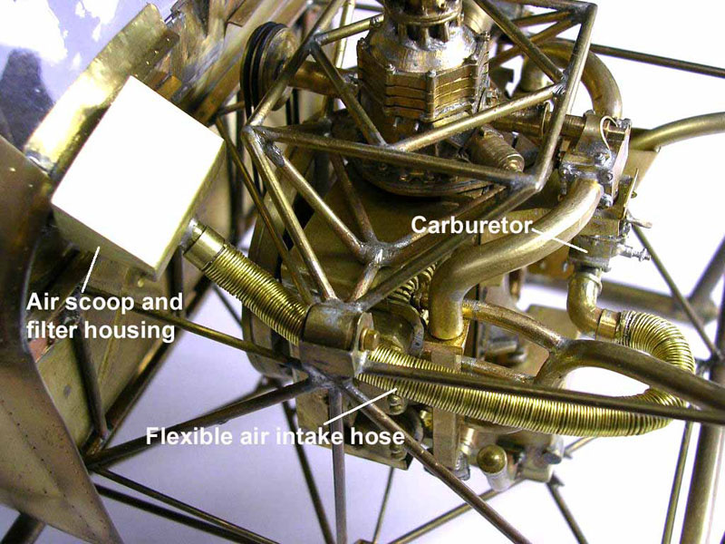
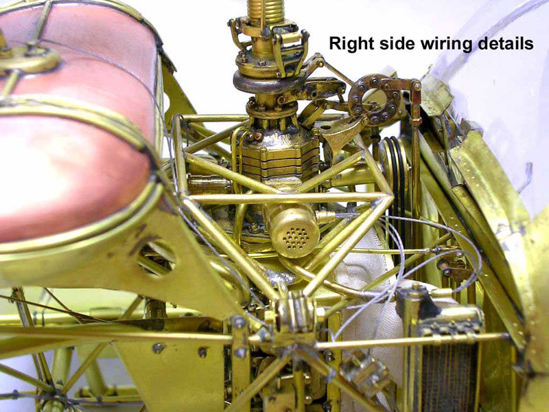
Engine Installation
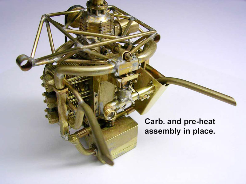
The engine was installed and plumbed.
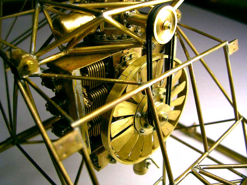
Engine Installation
In this view, you can see the detail of the cooling fan.
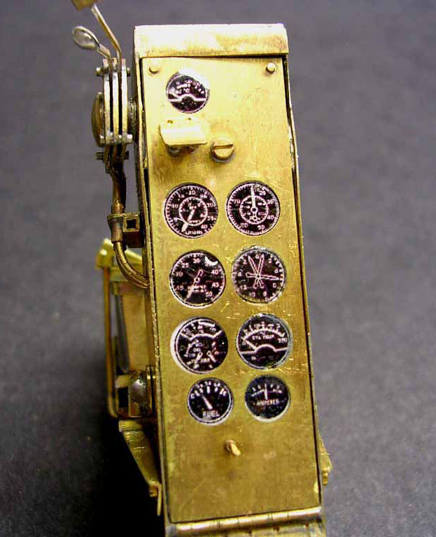
Bell H-13D Instruments
It’s the fine details that make a model like this so fun to admire. Note the instrument faces here.
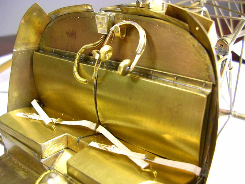
Bell H-13D Cockpit
Here you can see extra details with the pilot’s headphones hanging behind the seat.
Bell H-13D Rotor Assembly
The motor is installed here.
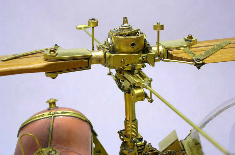
Bell H-13D Rotor Assembly
The rotor head is connected, and the blades are attached.
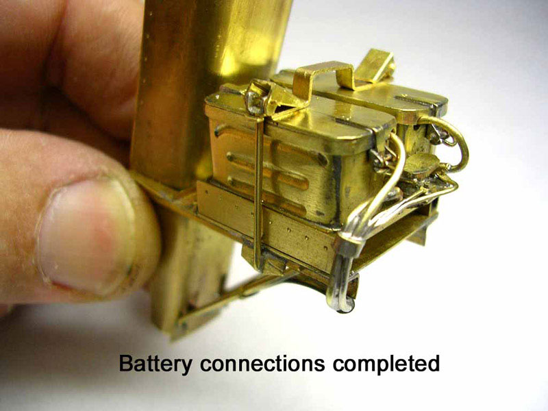
Bell H-13D Batteries
The batteries and their related wiring.
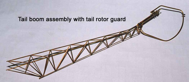
Bell H-13D Tail Construction
The tail is constructed of tiny tubing.
Bell H-13D Tail Construction
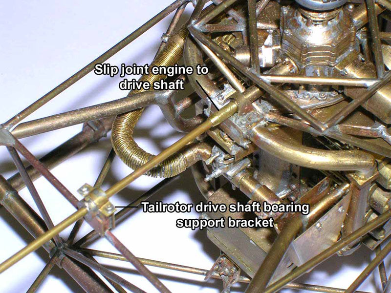
Once connected to the main body, the drive shaft components to the tail rotor are next.
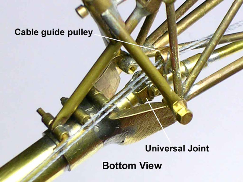
Bell H-13D Tail Construction
Details of the universal joint in the drive shaft to the tail rotor after installation.
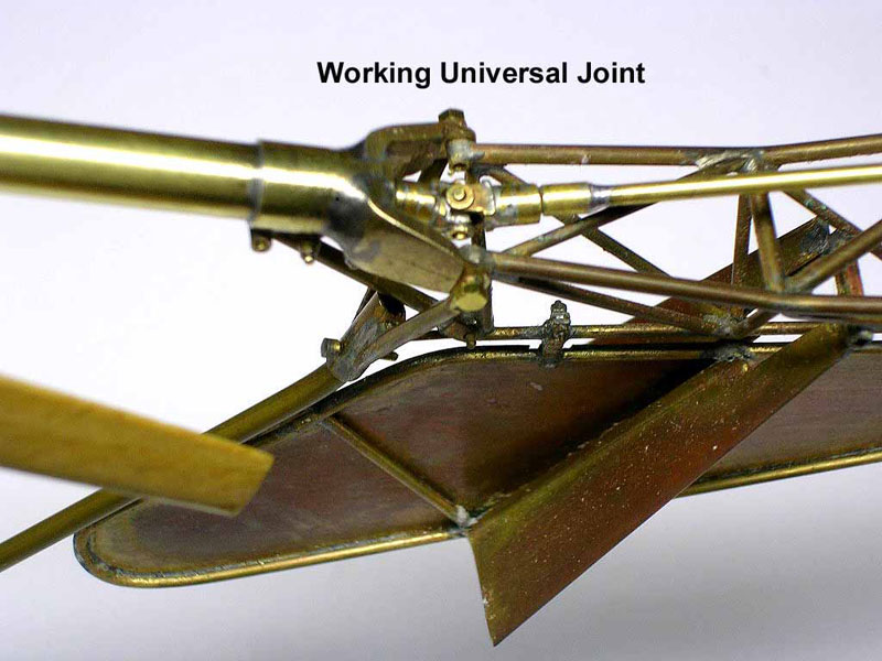
Bell H-13D Tail Construction
Another view of the universal joint.
Bell H-13D Tail Construction
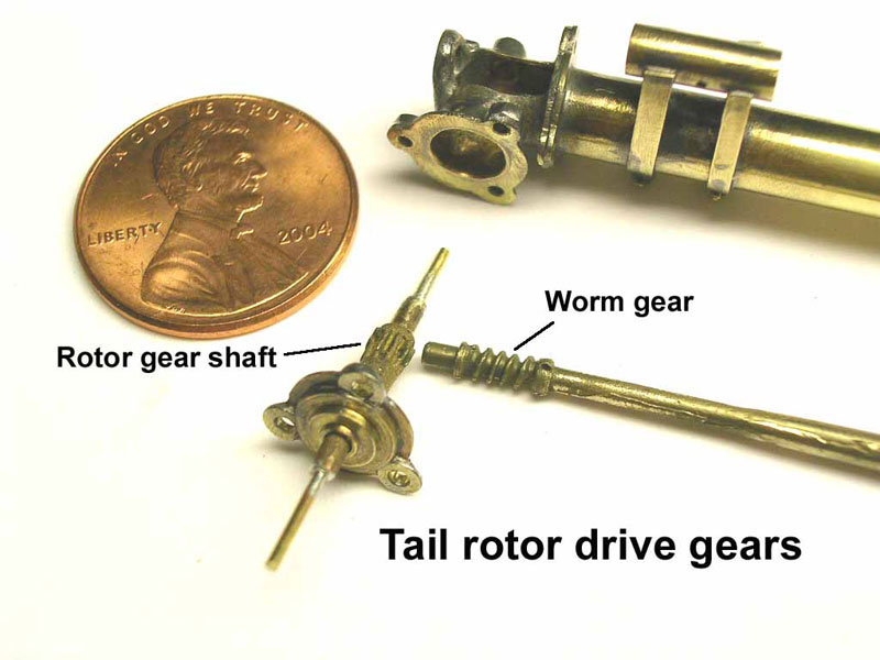
Details of the worm gear that drives the tail rotor.
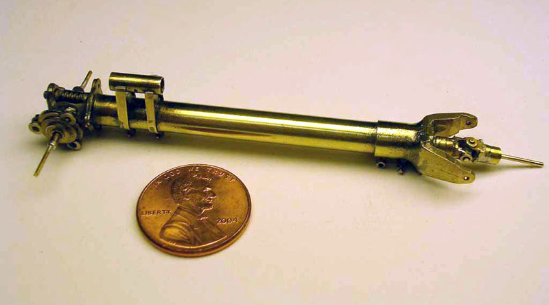
Bell H-13D Drive Shaft Unit
The completed drive shaft unit as an assembly.
WWI Fokker Aircraft
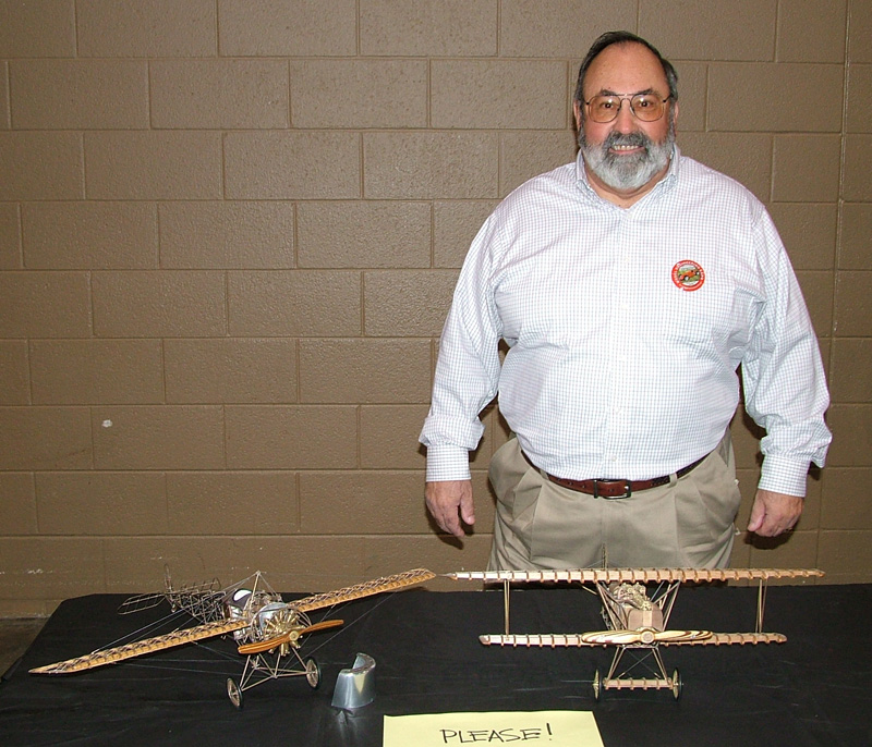
Ken With His Airplanes
Ken is pictured here displaying two of his models at the 2008 NAMES Expo in Toledo, OH. On the left is the Fokker Eindecker E-IV, and on the right is the Fokker D-VII.
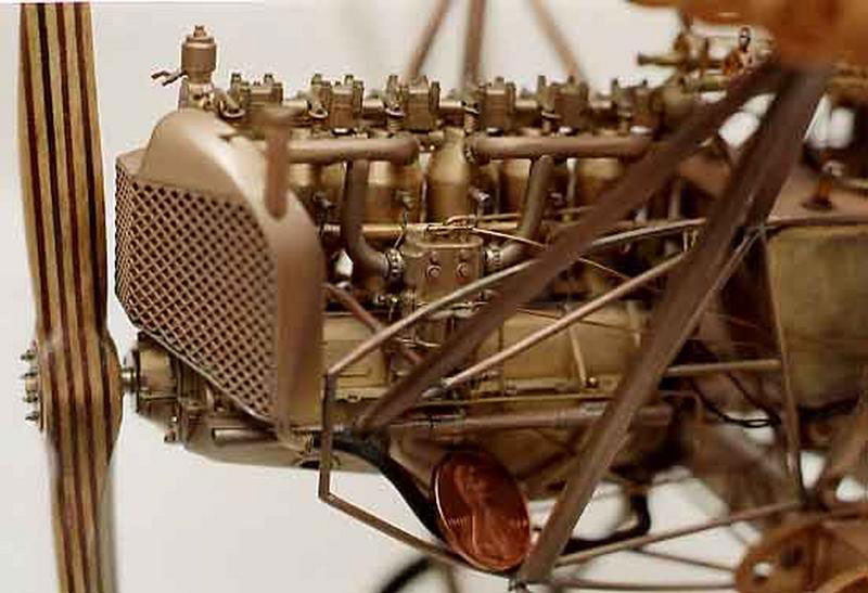
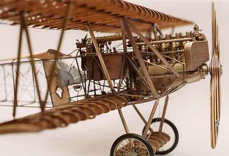
Fokker D-VII
Detail view of the engine and propeller on the Fokker D-VII.
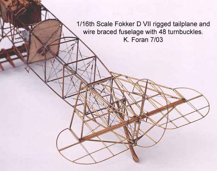
Fokker D-VII
Tail and fuselage details.
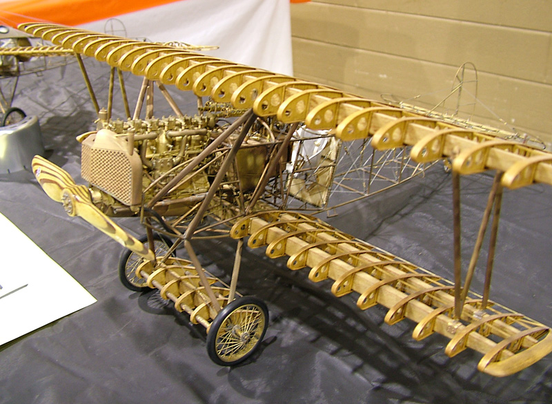
Fokker D-VII
Side view of the Fokker D-VII.
Fokker D-VII
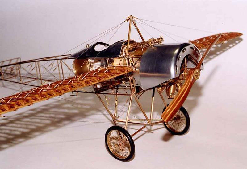
Fokker Eindecker E-IV
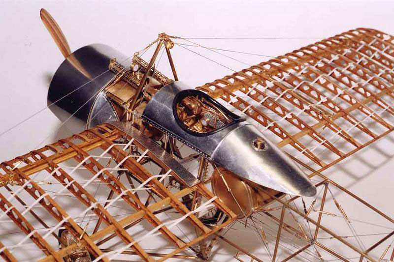
Fokker Eindecker E-IV
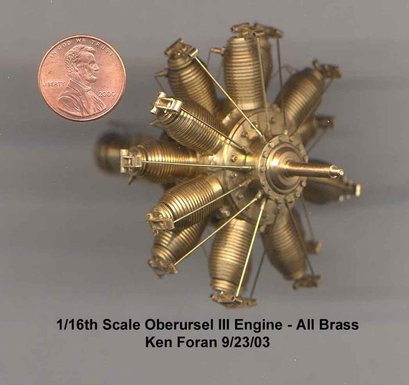
Fokker Eindecker E-IV Engine
A close view of the engine built for this model.
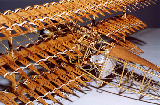
Fokker DR-I Triplane
Note the level of detail.
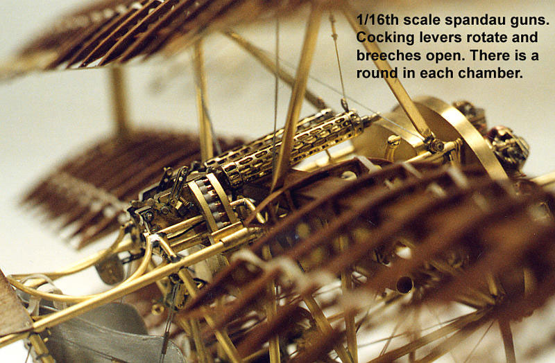
Fokker DR-I Triplane
A close look at the 1/16 scale Spandau guns.
1/15 Scale N2S Stearman Biplane
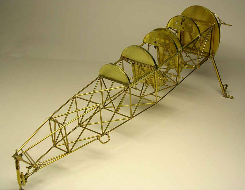
N2S Stearman Biplane
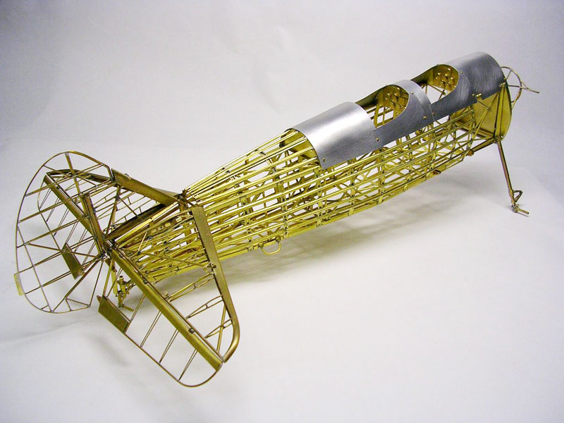
Ken’s latest project is the N2S Stearman Biplane in 1/15 scale. In this photo the basic fuselage boxed structure is taking shape.
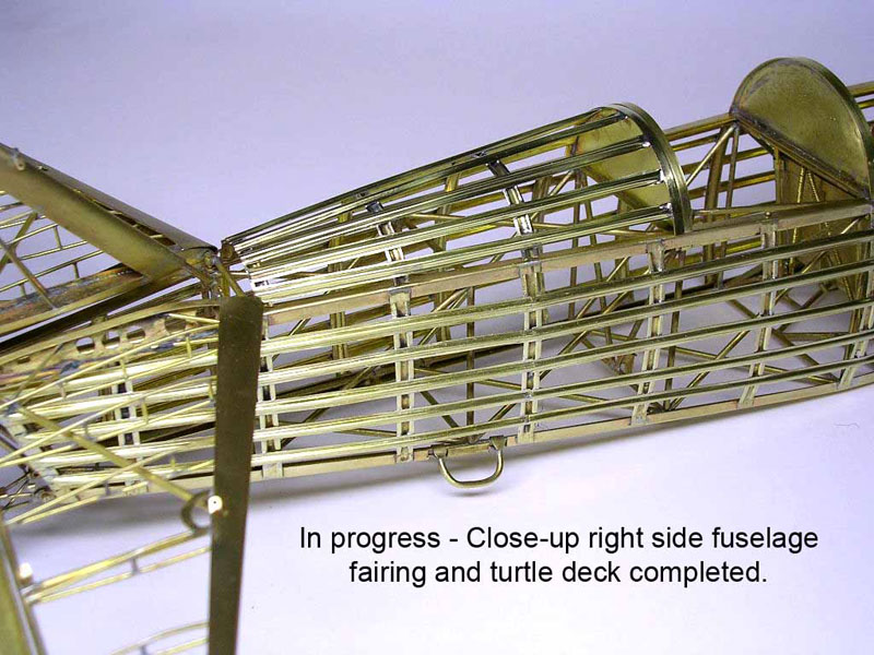
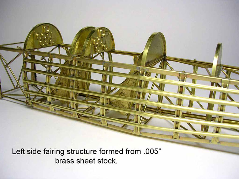
N2S Stearman Biplane
Here the stringers were applied to the sides and top to further form the shape.
N2S Stearman Biplane
This photo also shows the instrument panel with instrument faces.
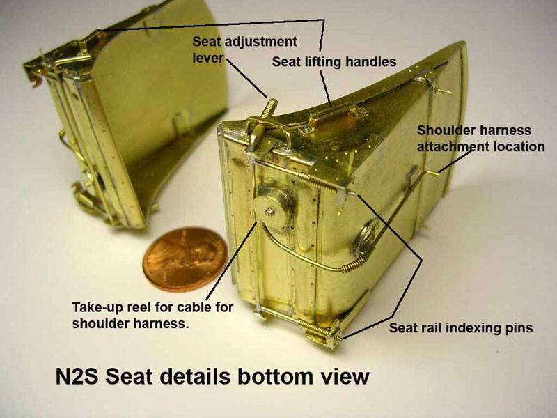
N2S Stearman Biplane Seats
The pilot and passenger seats are shown here, with a penny for reference.
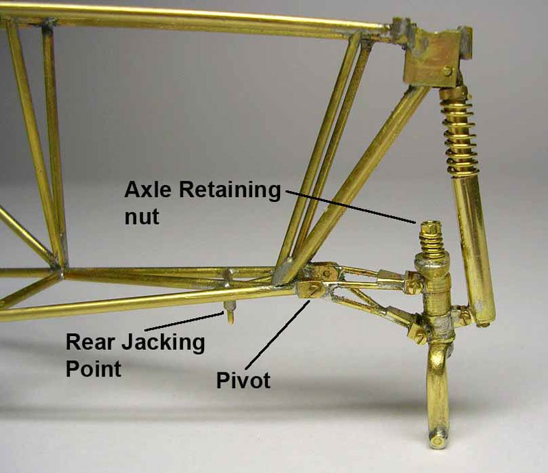
N2S Stearman Biplane Suspension
Suspension for the wheels of the biplane.
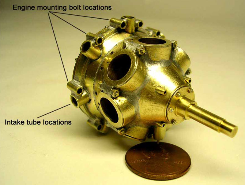
Continental R-670 Engine
The Continental R-670 7-cylinder radial engine begins to take shape.
Continental R-670 Engine
Many different machined shapes are soldered together to form the crankcase.
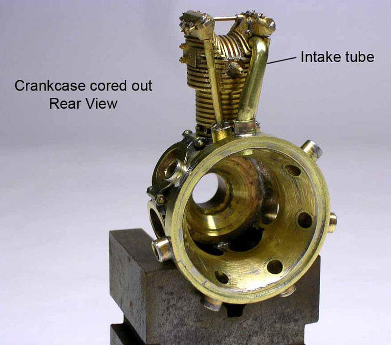
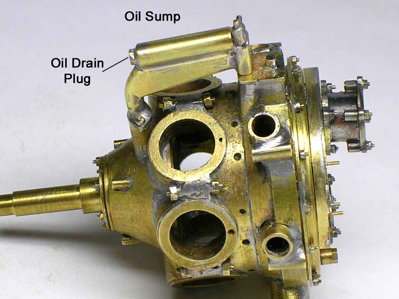
Continental R-670 Engine
Rear view of the crankcase.
Engine Components
This photo shows many of the other components that will make up the Continental engine.
Continental R-670 Engine
The partially assembled engine with one typical head, and valve assembly attached.
Continental R-670 Engine
Here the engine is attached to the firewall.
N2S Stearman Biplane Fuselage
The forward part of the fuselage, with the center section of the upper wing in place.
N2S Stearman Biplane
This photo shows the gas tank formed into the upper wing center section.
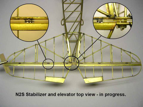
N2S Stearman Biplane Tail
Details of the tail section show closeups of the hinges for the elevator.
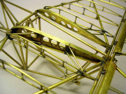
N2S Stearman Biplane Stabilizer
Closeup of the center of the horizontal stabilizer.
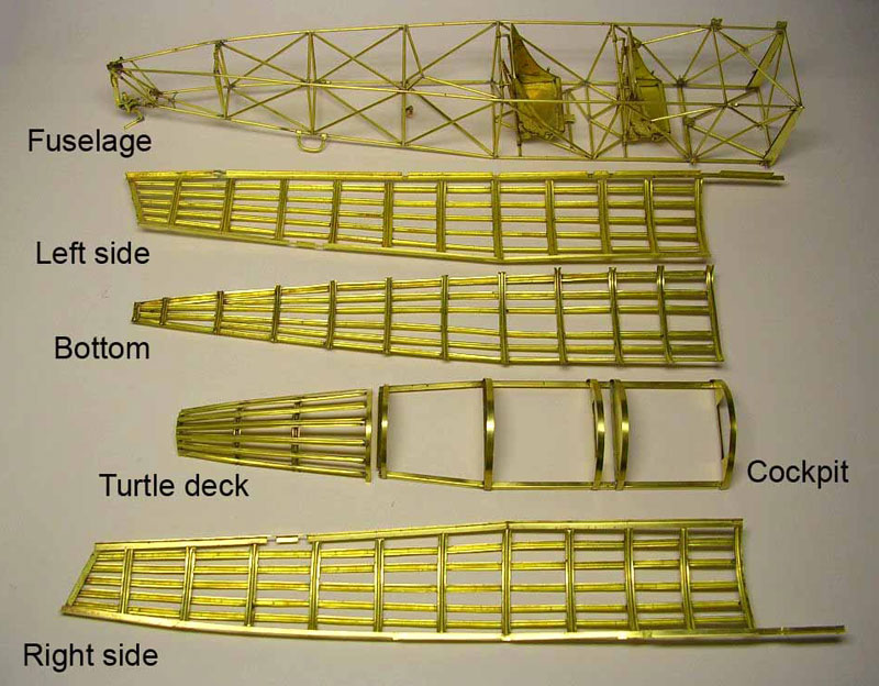
N2S Stearman Biplane Fuselage
The basic fuselage, and the various deck structures that give it a rounded shape.
N2S Stearman Biplane Fuselage
This photo shows the structures in place, with some of the aluminum bodywork around the cockpit also added.
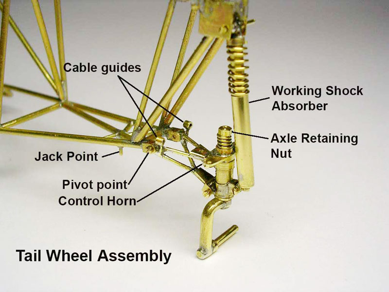
N2S Stearman Biplane Tail Wheel
The tail wheel has quite a sophisticated little shock absorber system, all of which is duplicated in miniature and actually functions.
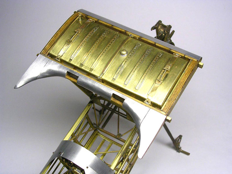
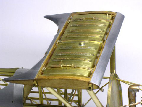
N2S Stearman Biplane Gas Tank
The gas tank in the center of the upper wing is shown from the top.
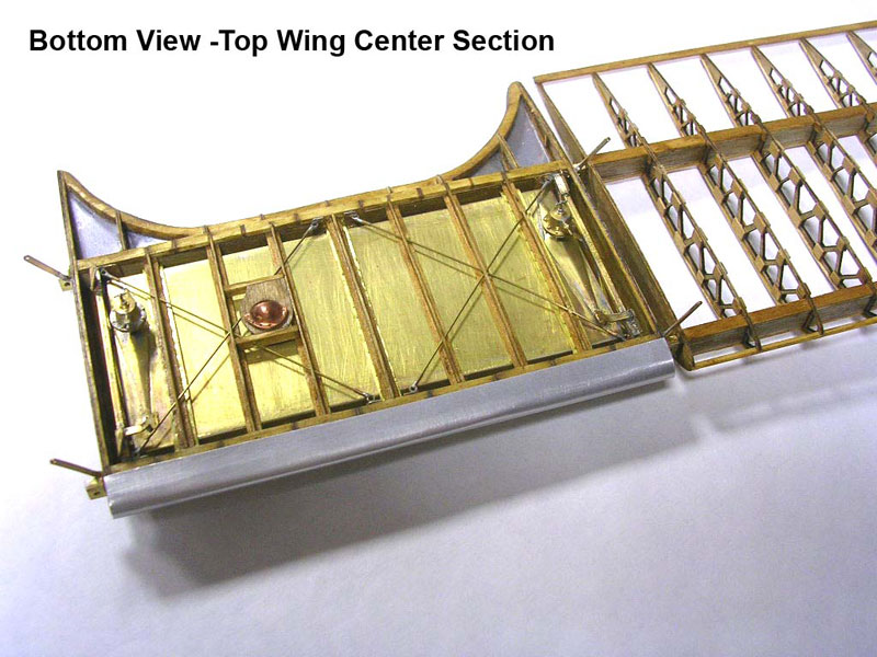
N2S Stearman Biplane Gas Tank
Here the gas tank is shown from the bottom view.
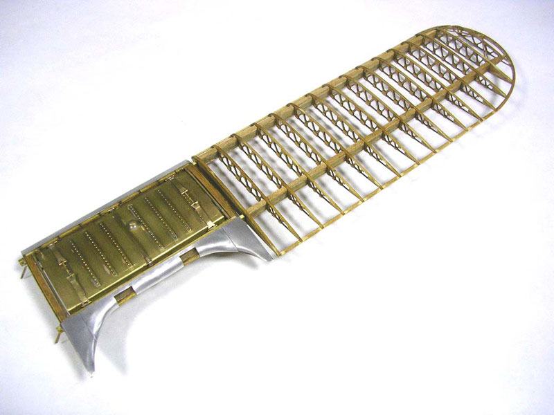
N2S Stearman Biplane Wing
The upper wing sections are nearing completion. Each rib is laser cut, and then reinforcement plates are applied. The leading edge of the wing will be aluminum covered like the center section. The spars have a brass rectangular tube for rigidity, and are laminated with 1/64 scale plywood on the sides and top.
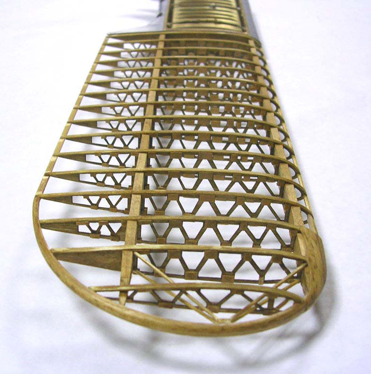
N2S Stearman Biplane Wing
Top and bottom caps of wood are cut to length between the ribs. Ken uses this technique on biplane wings to eliminate wing deflection and sag over time.
1/8 Scale Ford Model T Board Track Racer
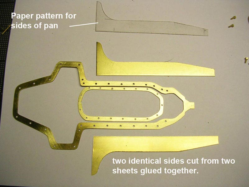
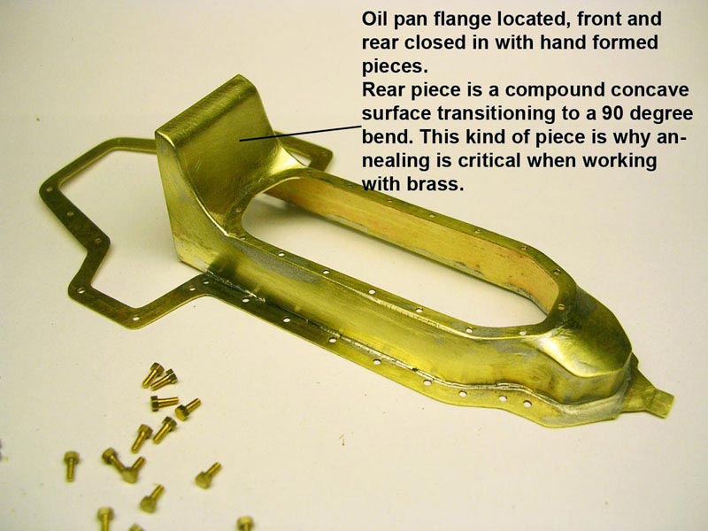
Oil Pan Construction
The following photos document the sequence for making the oil pan from sheet brass.
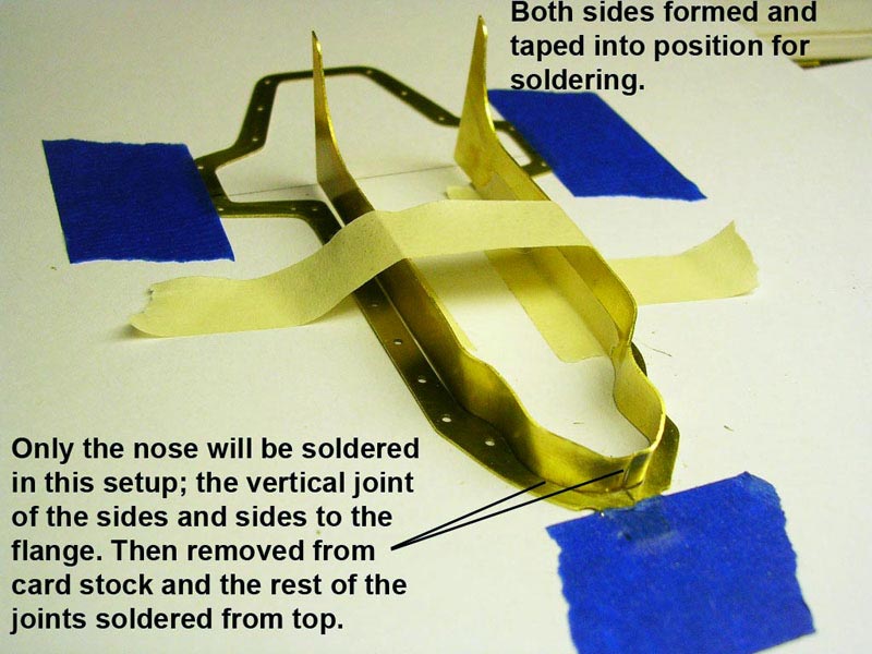
Oil Pan Construction
The notes that Ken has added to the photos provide some useful information for modelers.
Oil Pan Construction
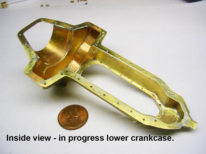
Oil Pan Construction
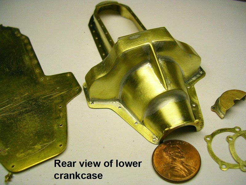
Oil Pan Construction
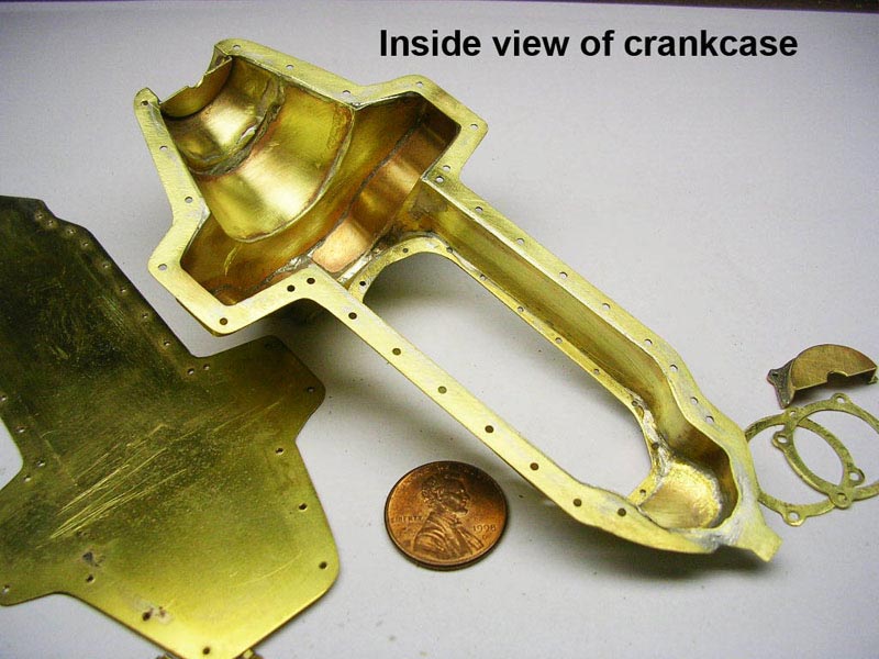
Oil Pan Construction
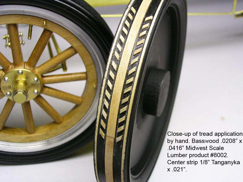
Model T Wheels
The tires are actually made from wood, although once painted satin black they look like rubber. Here you see the tread being applied. If you think there is a quick way to achieve this, forget it. Each piece of the tread pattern is made and glued on individually, before being painted black.
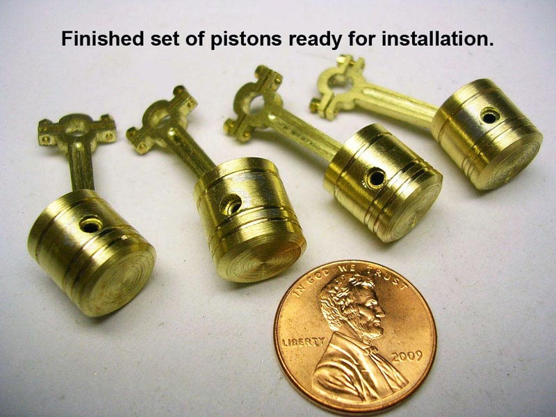
Model T Pistons
A set of four pistons and connecting rods are shown compared to a penny for scale reference.
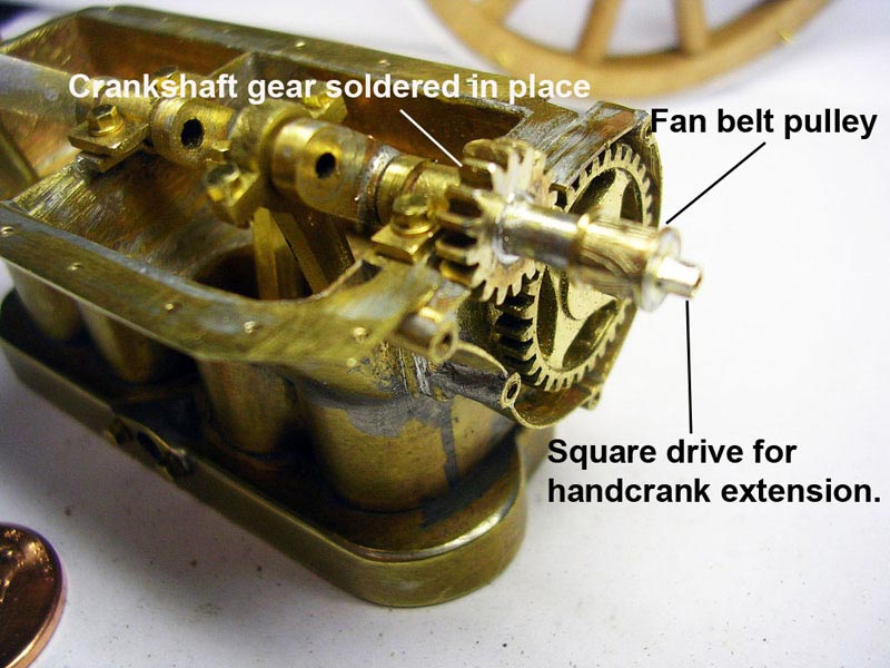
Crankshaft Installation
The crankshaft is installed in the block. This photo shows the connecting rods in place on their journals.
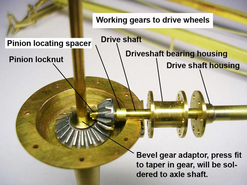
Model T Differential
The differential contains bevel gears that drive the rear axle, just like the real thing.
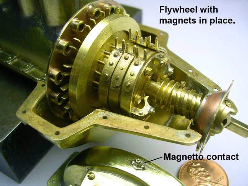
Model T Transmission
This detail shows the bands on the transmission, and the magnets for the magneto on the flywheel. The magneto contact is shown on the transmission housing at the bottom.
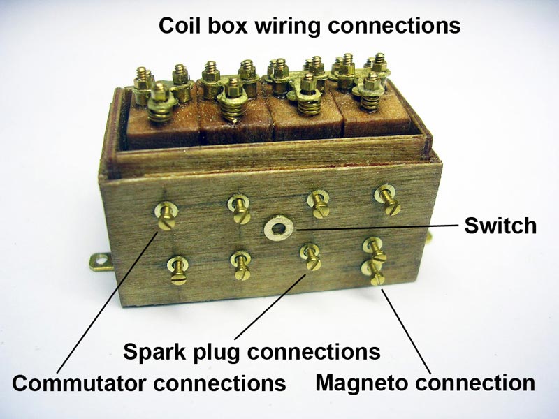
Model T Coil Box
The coil box and connections.
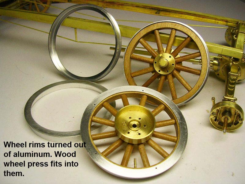
Model T Wheels
The wheels were made using aluminum rims and wooden spokes. The Model T was modern in many ways, but in others it was still using outdated buggy technology.
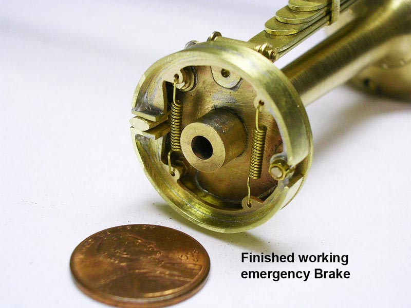
Model T Brakes
The brakes and springs for the emergency brakes actually work.
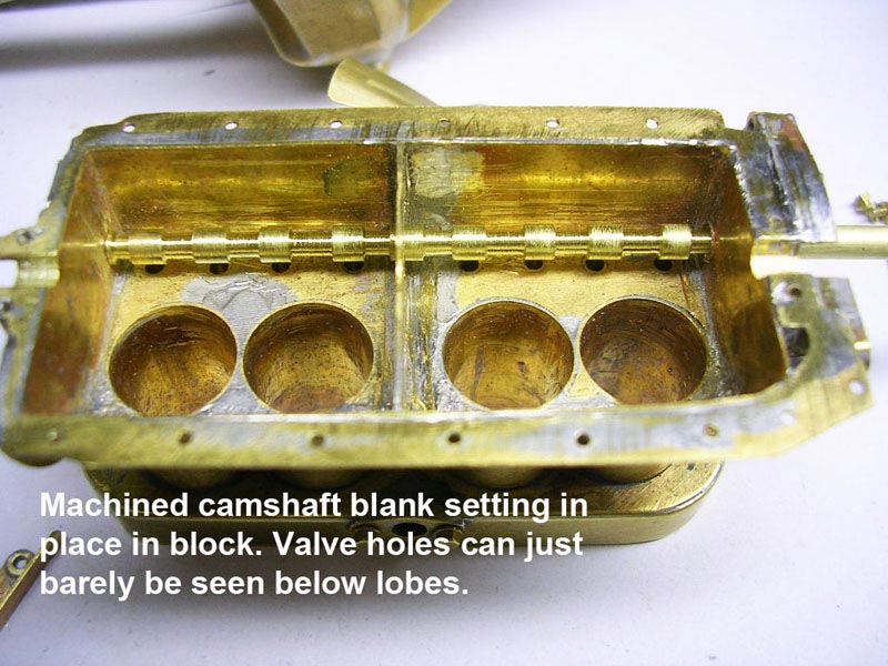
Model T Engine Block
The engine block with turned camshaft in place. The cam lobes really do actuate the valves.
Model T Engine
Model T Engine
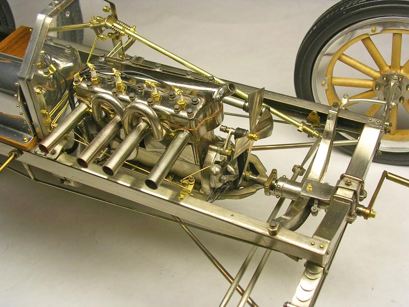
Finished Model T Engine and Frame
The finished, nickel-plated engine and frame.
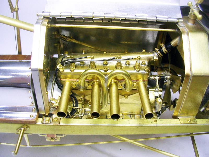
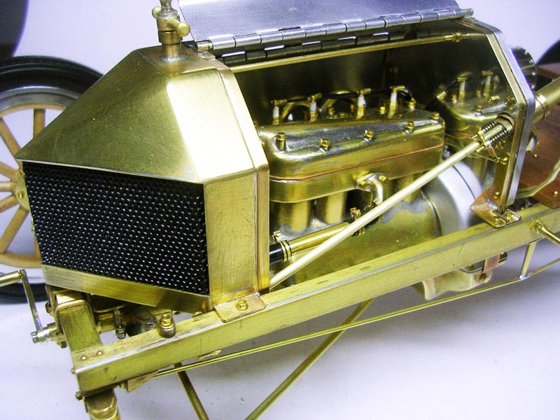
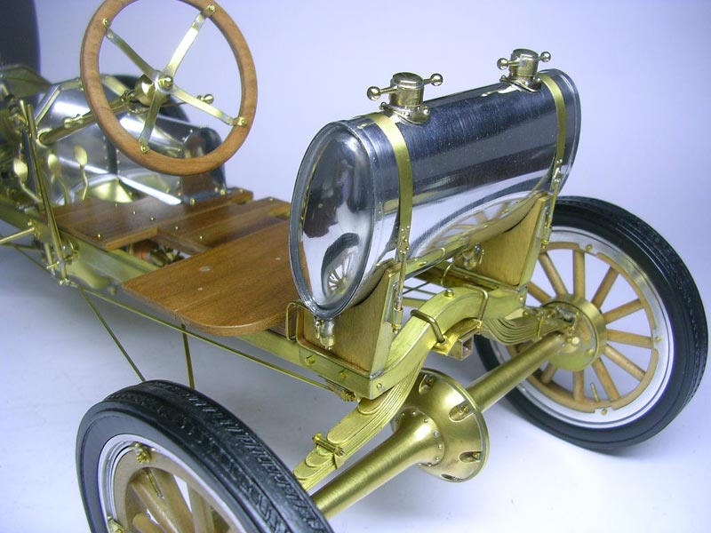
Model T Progress
The radiator is in place, and the engine cover with piano hinge is mounted.
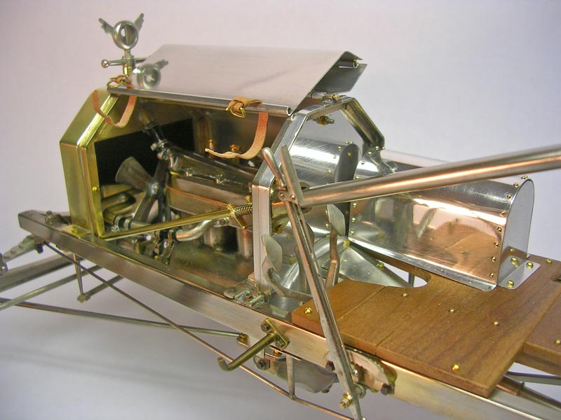
Model T Fuel Tank
The fuel tank sits right behind the driver and ride-along mechanic seats.
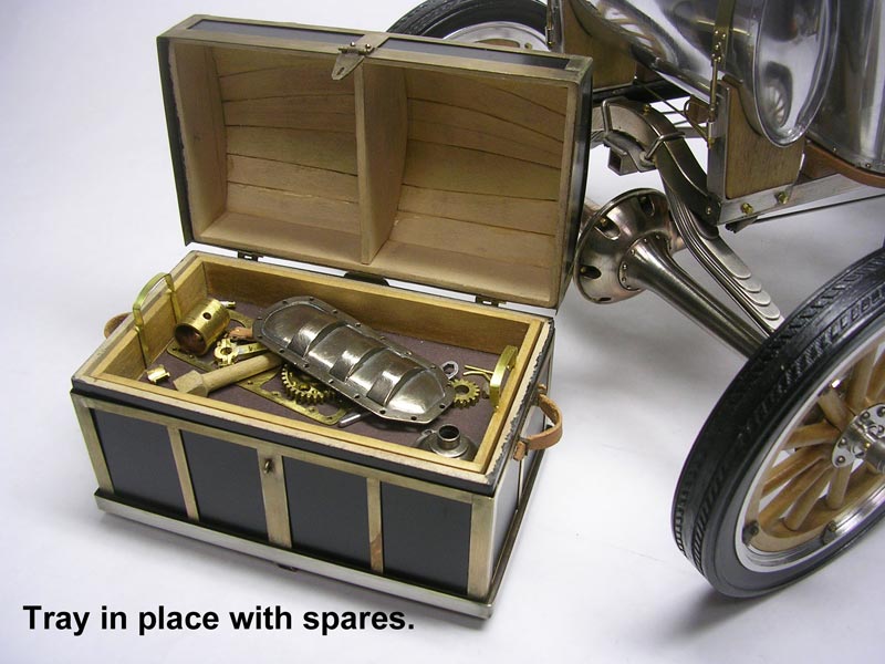
Model T Trunk
The trunk is made from wood with a framework of brass. In the top tray are some spare parts, but underneath is a hidden battery powered sound module. The module plays the sound of a real Model T, starting up and idling, when a button on the bottom is pushed. The trunk is normally mounted behind the rear axle.
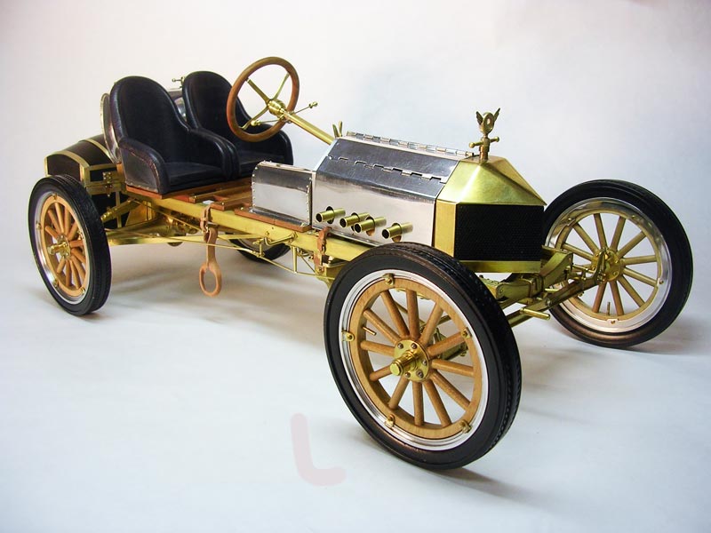
1/8 Scale Ford Model T Board Track Racer
Ken’s scale Ford Model T board track racer.
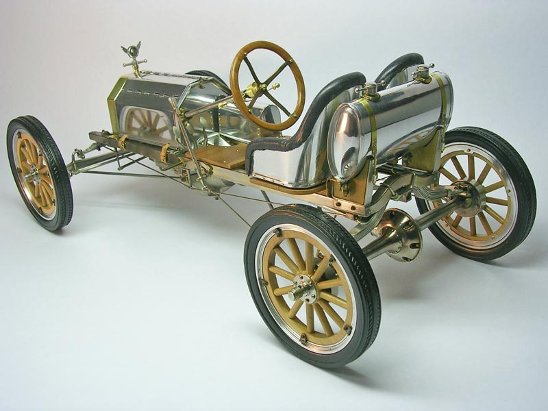
1/8 Scale Ford Model T Board Track Racer
A rear view of the finished Model T.
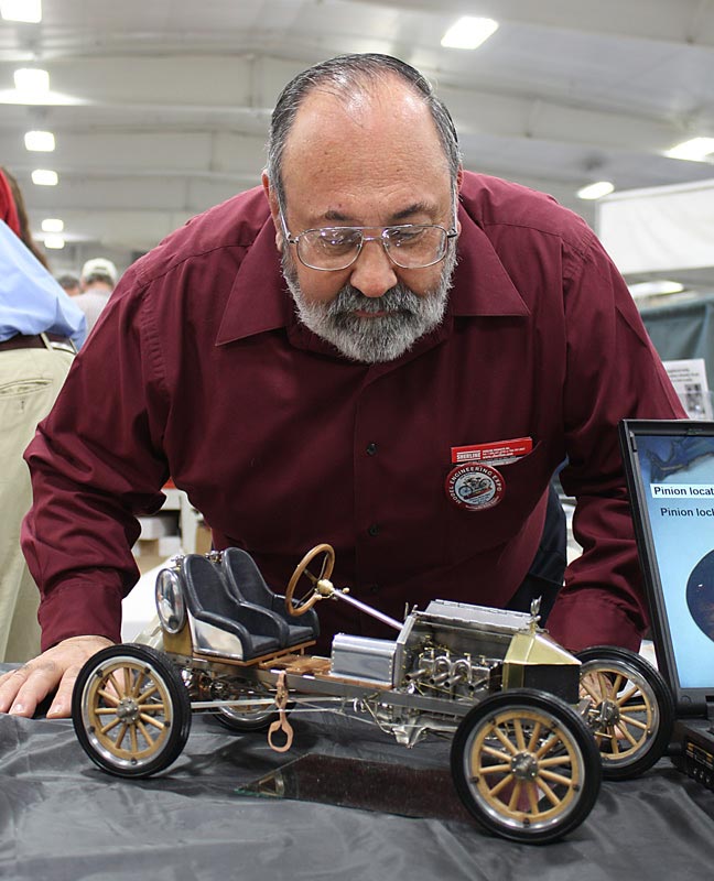
Ken With His Model T
Ken looking over his Model T while it was on display at the NAMES Expo in Detroit, April 23, 2010. Ken was kind enough to display it at the Joe Martin Foundation booth for spectators to enjoy.
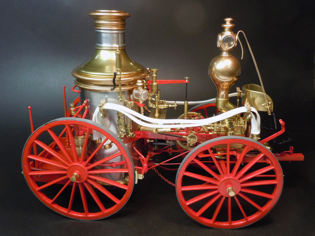
1/12 Scale 1869 Allerton Steam Pumper Fire Engine and 1890 Ladder Wagon
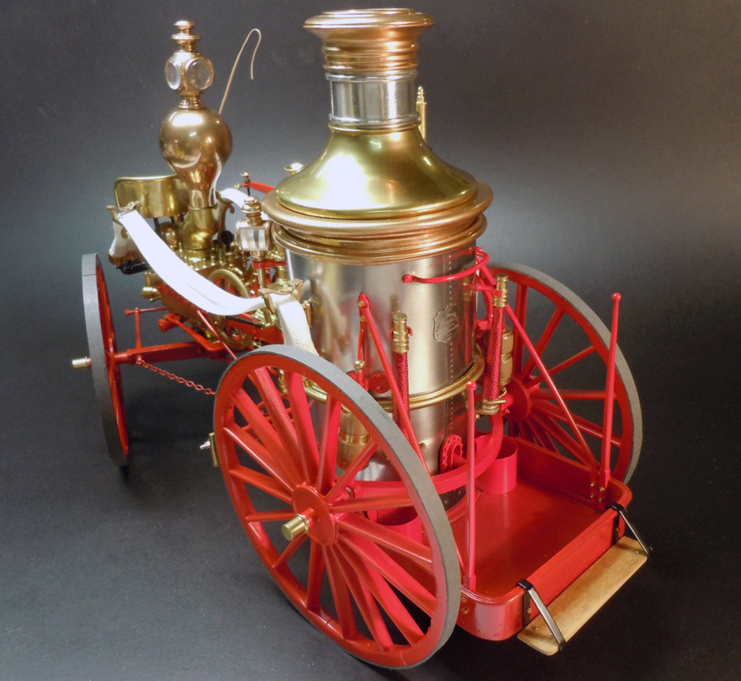
Allerton Steam Pumper
This model was designed and completed to be offered as a kit by Model Expo. This was the first model to be built from the actual kit parts as “proof of manufacture.”
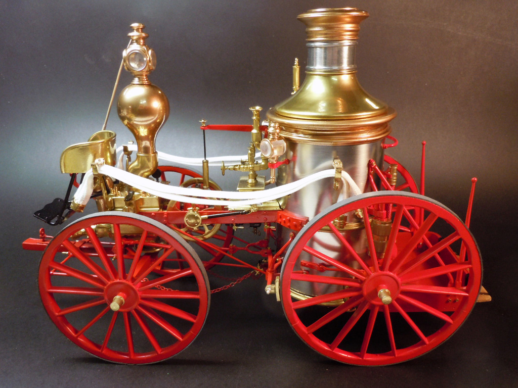
Allerton Steam Pumper
Allerton Steam Pumper
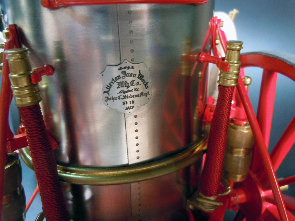
Allerton Steam Pumper
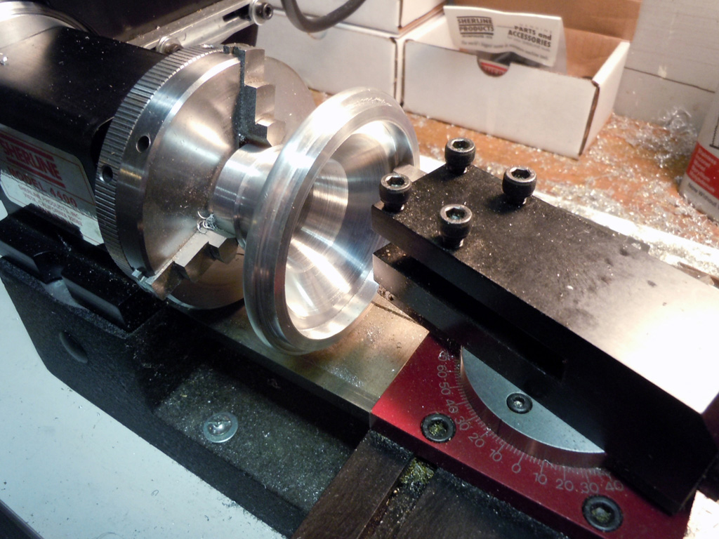
Boiler Cap Construction
Here are a few shots of the boiler cap being turned on a Sherline lathe.
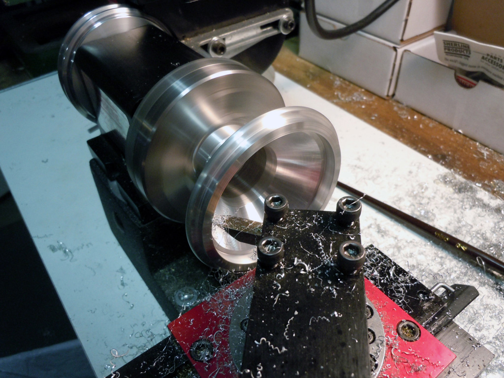
Boiler Cap Construction
Ken used a compound slide to achieve the inner taper.
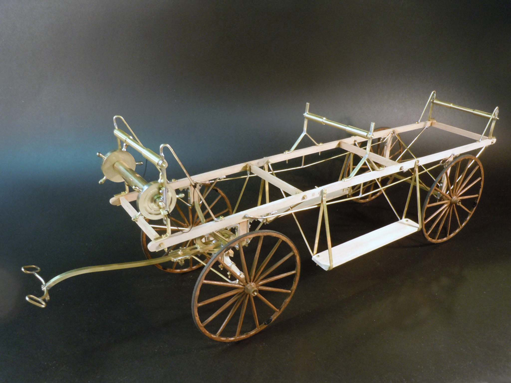
1890 Ladder Wagon
Another kit prototype that Ken was working on for Model Expo, which also involves vintage firefighting equipment. This ladder wagon was coming along nicely (as of 2014).