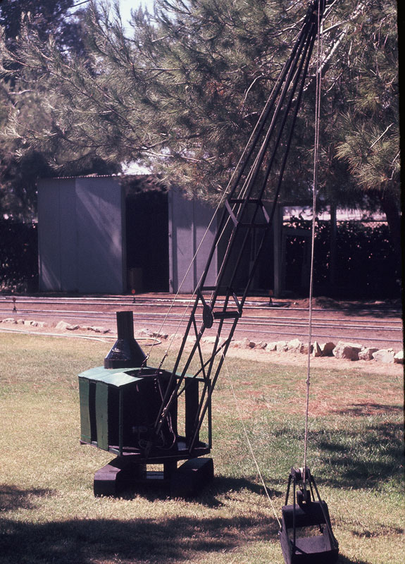
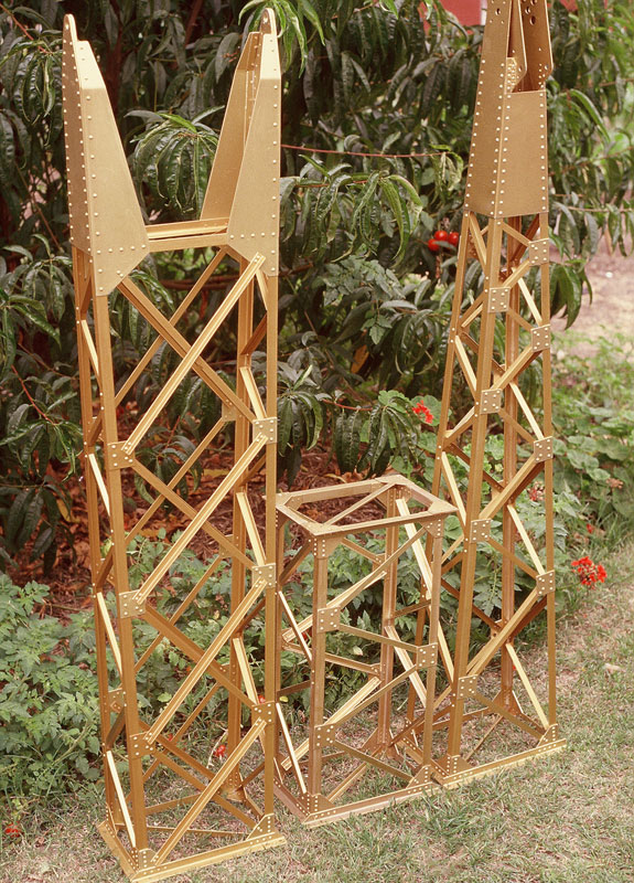
Wooden Crane Mock-Up
This wood and cardboard mock-up shown at the Los Angeles Live Steamers event in July, 1972, was used for confirming the size.
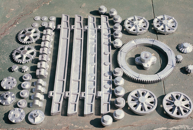
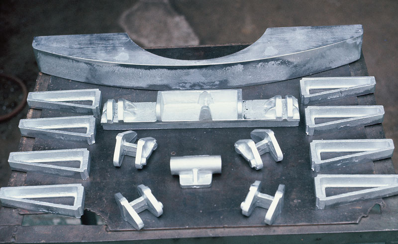
Castings for Travel Base
Sixty-two zinc alloy castings for the travel base. Note the swing bull gear in eight sections.
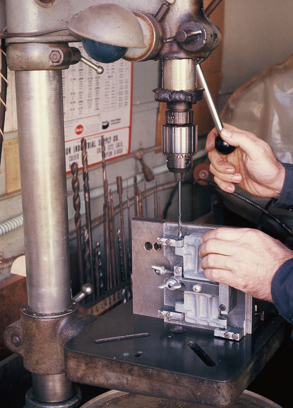
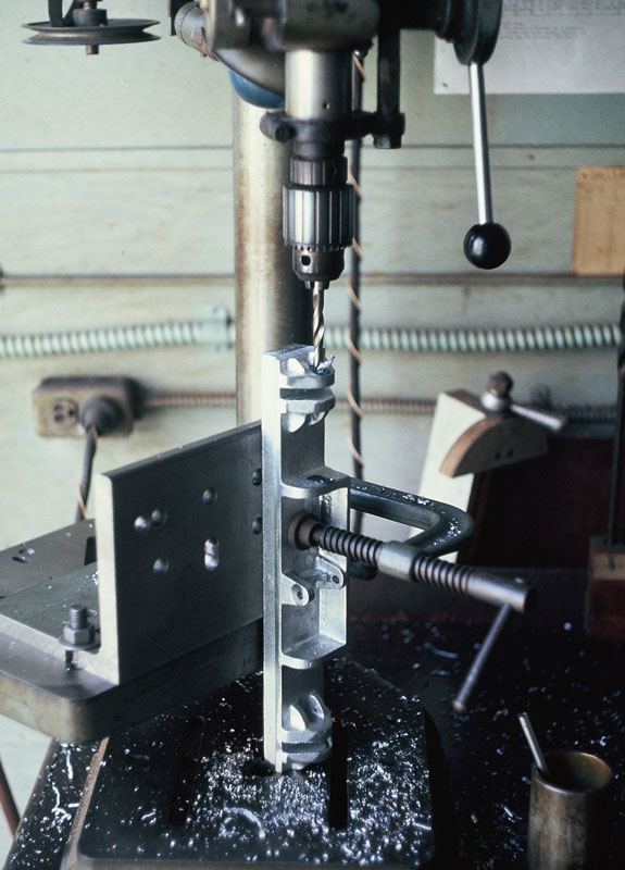
Drilling the Hinge Pin Holes
Jerry drills the hinge pin holes in the track pads. Since all the holes in 58 castings had to be parallel, this was the most elaborate piece of tooling for the entire project.
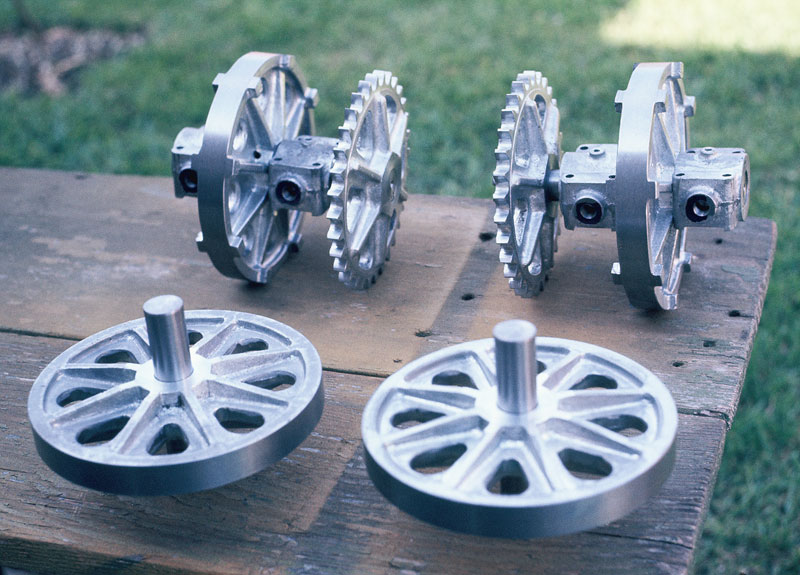
Cast Bull Wheels
The cast bull wheels and associated parts.
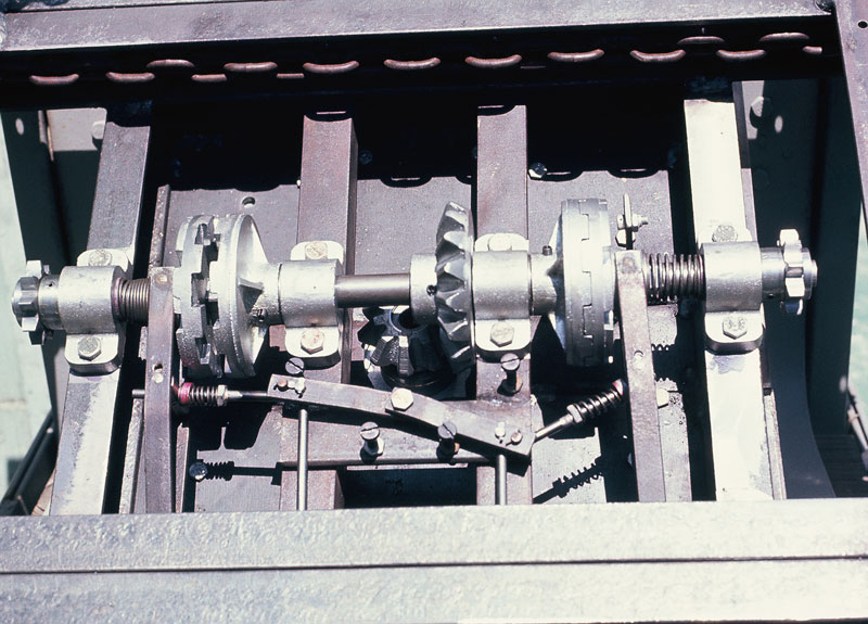
Lower Propel Shaft
This underside view of the lower propel shaft shows the jaw clutches for steering.
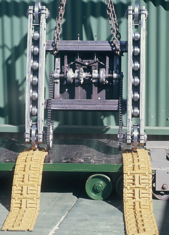
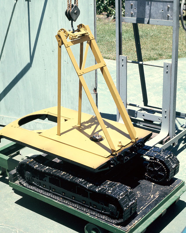
Travel Base
A chain hoist is now needed to lift the unpainted travel base while it is set onto the tracks for testing.
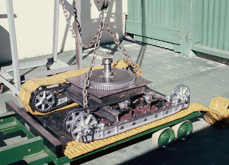
Fitting the Tracks
The shop hoist aids in fitting the tracks.
Primer Coating
The primer coat of paint is applied.
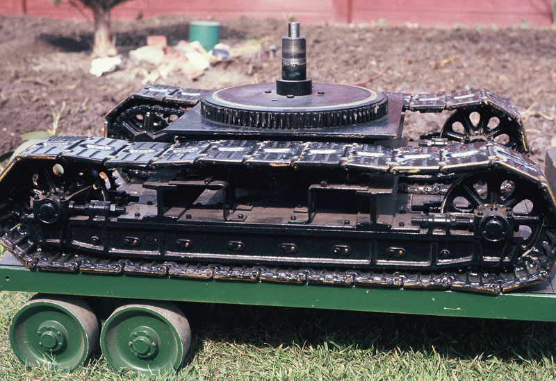
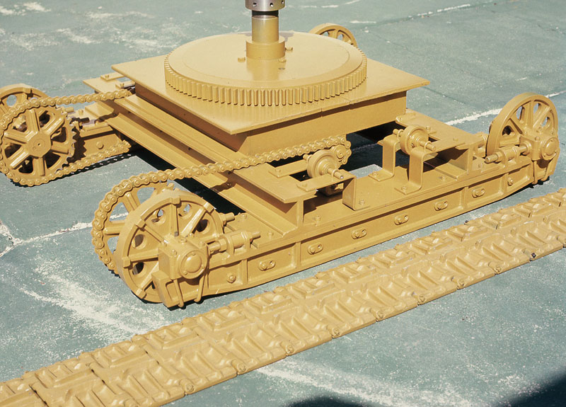
Completed Travel Base
The completed travel base showing a hand crank on the vertical shaft for demonstrating the action.
Frame Castings
Castings for the revolving frame.
Drilling for Hinge Pins
Drilling the boom foot casting for the hinge pins.
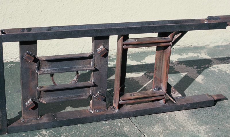
Welded Frame
A bottom view of the welded frame.
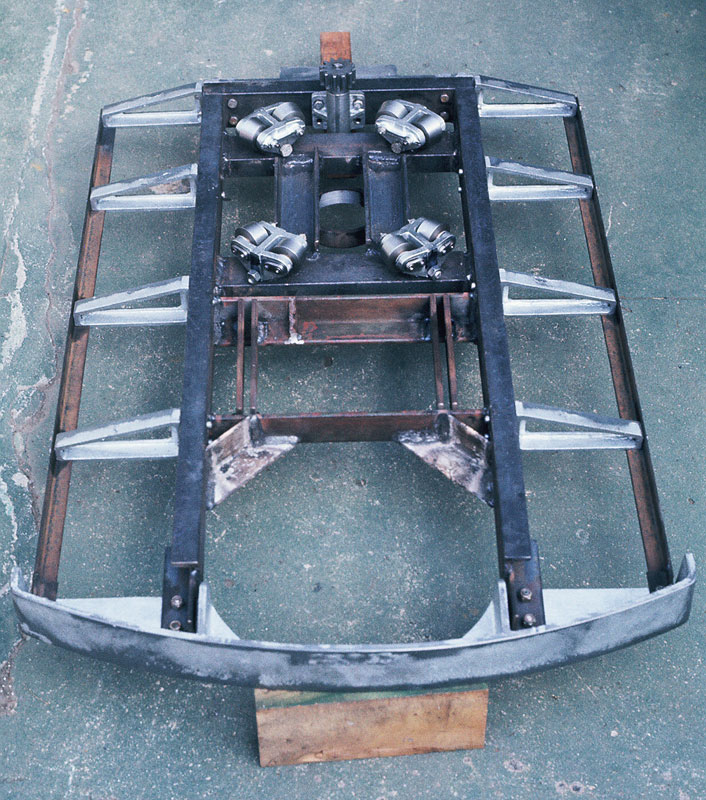
Welded Frame
A bottom view of the frame shows the four conical rollers, side extensions, and the rear crossmember.
Mounting Frame to Base
The primered revolving frame is fitted to the travel base.
Piston and Rod Parts
The original pistons shown here were made from cast iron. The engine is now fitted with brass pistons with Teflon rings.
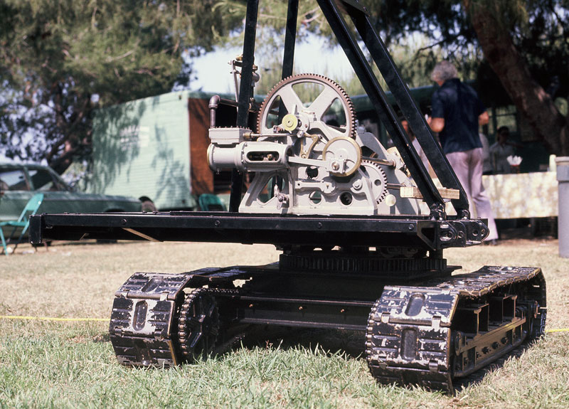
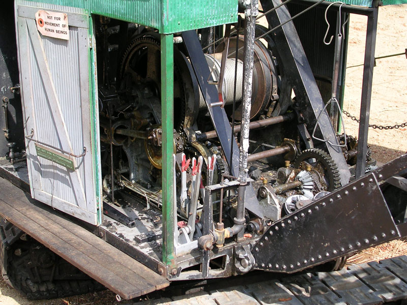
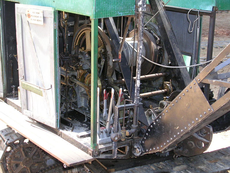
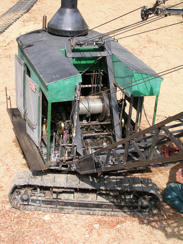
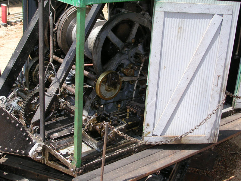
Main Engine and Gearing
By May, 1975 the main engine and gearing were complete, and could propel the machine using compressed air.
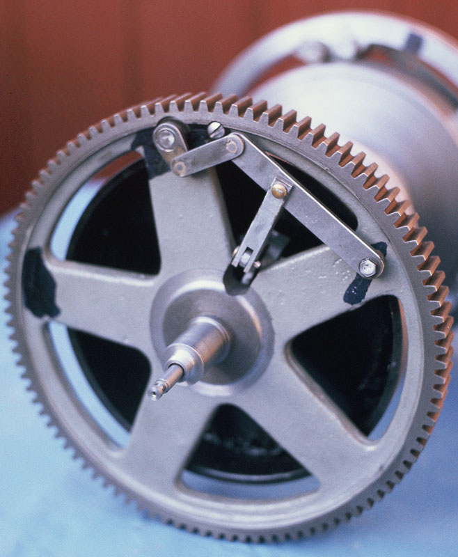
Hoist Drum
The hoist drum, showing the actuating mechanism for the clutch band.
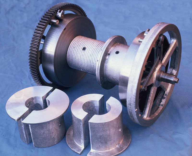
Clutch and Brake Drums
The clutch and brake drums with laggings for hoist cables. The dragline lagging is mounted—the symmetrical set is for clamshell work. (All laggings have since been grooved.)
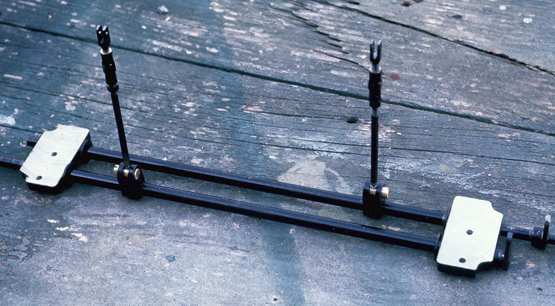
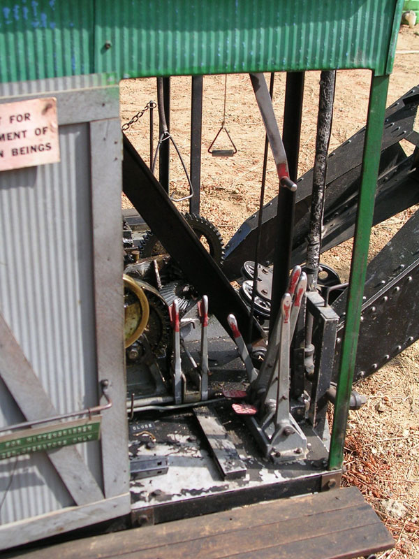
Cross Shafts
The cross shafts for brake and clutch control. Mounting these under the frame was one of the toughest jobs because there was already much in the area where they had to go.
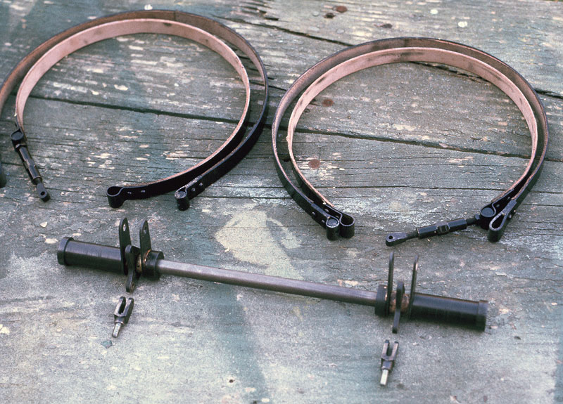
Frictions
Frictions (bands) with their leather linings.
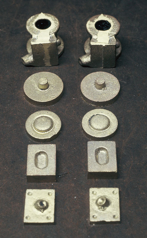
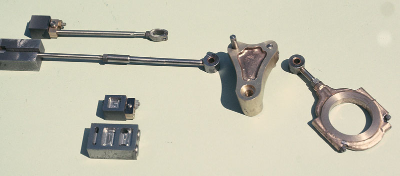
Brass Castings
The brass castings for the steam cylinders (rams) that operate the drum clutches. They are somewhat similar to the power reverse gear on a locomotive.
Machined Parts
The machined parts. Surprisingly, with all the guesswork involved, they worked, giving a useful mechanical advantage.
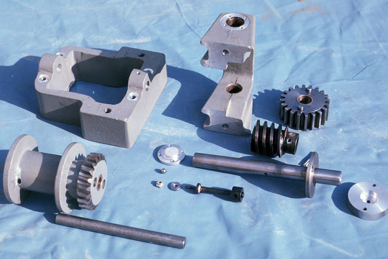
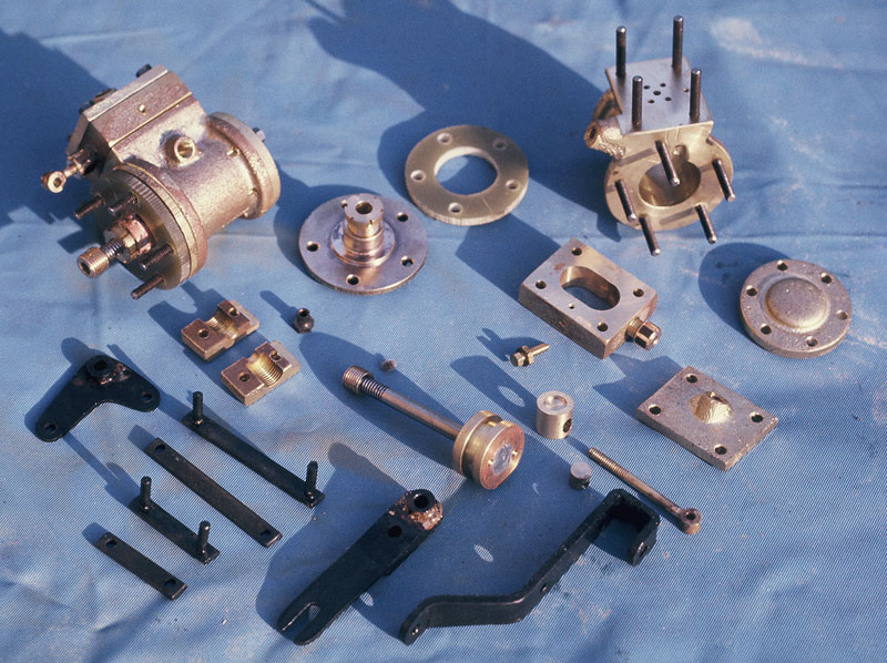
Boom Hoist Parts
Parts of the worm driven boom hoist.
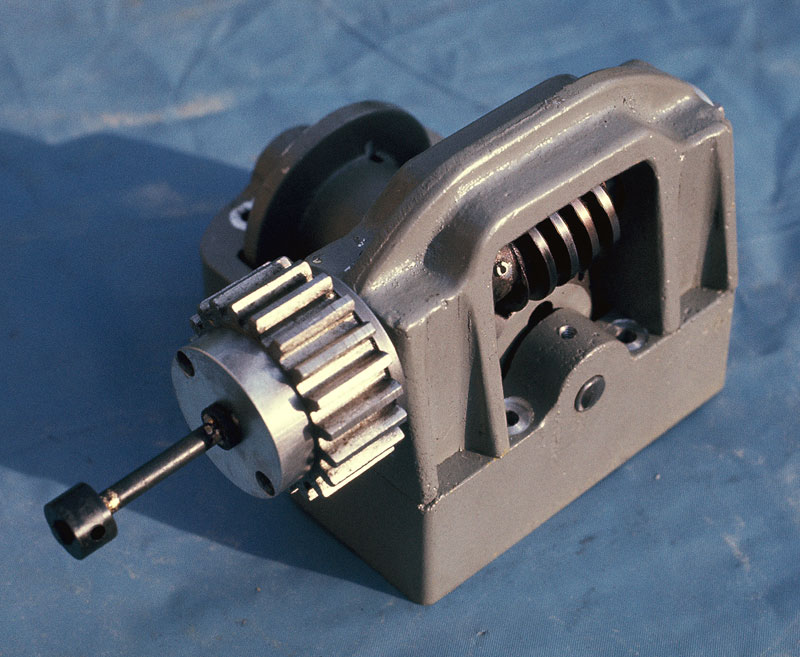
Assembled Boom Hoist
The boom hoist, assembled.
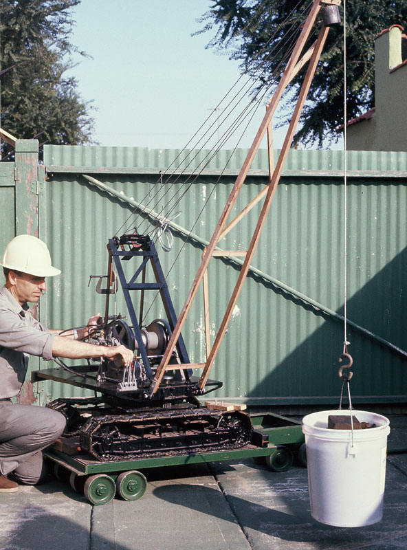
Jerry Testing the Crane
Jerry runs an operational test using 35 psi of air pressure to the engine to pick up a 35 pound load. The tipping point was 5 feet from the center post with no counterweight, an encouraging result.
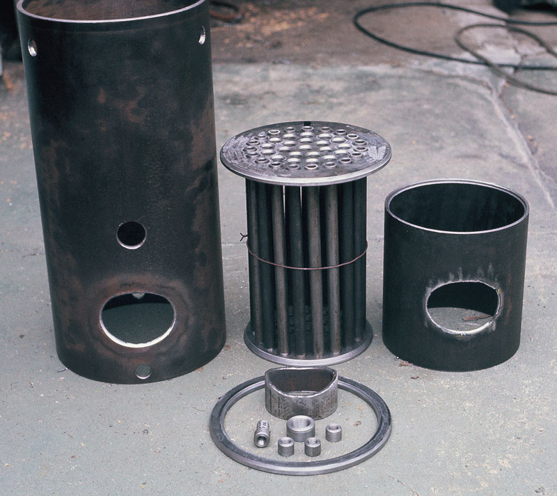
Boiler Parts
The original boiler parts ready for welding. As mentioned in the article, the rust-prone steel boiler was later replaced with a copper one.
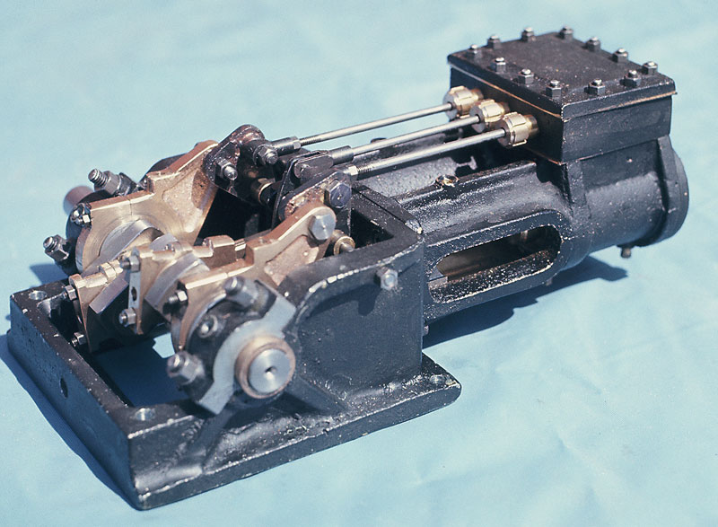
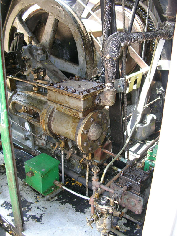
Slewing Engine
The slewing engine departs from full-size practice by using a 2-piece design to simplify foundry and machining procedures.
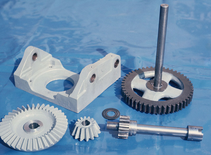
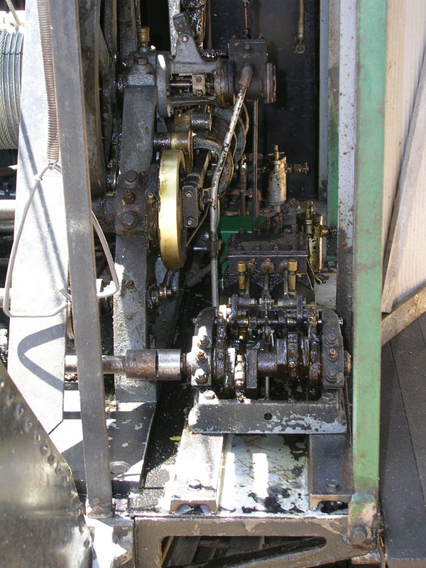
Gear Train
The swing engine gear train.
Boom Sections
The completed boom sections primed for painting. The total length when assembled is 10 feet, which corresponds to 60 feet on the full-size version.
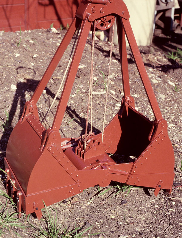
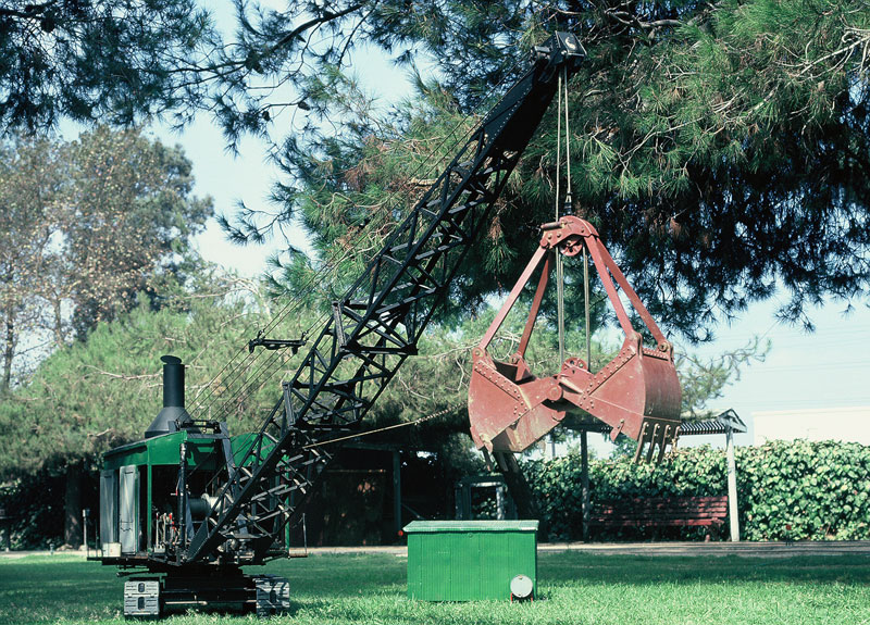
Assembled Clam Bucket
When assembled, a piece of old sash cord was hastily reeved to see what 45 pounds of bucket could do. What it did was break the cord, but not before its digging ability was proved. The seeming paradox of an upward pull making these things dig into the ground is explained by the multiple parts of the closing line, which greatly reduces this force—plus the counterweight and the weight of the bucket itself. Assisted by the rather fierce looking teeth, even this miniature bucket can dig quite respectably in any reasonable soil.
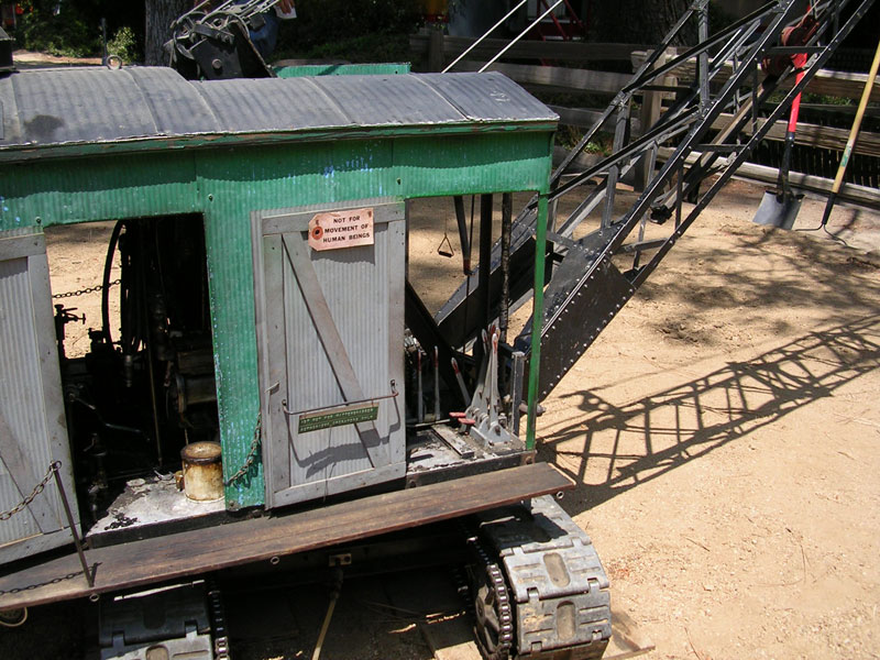
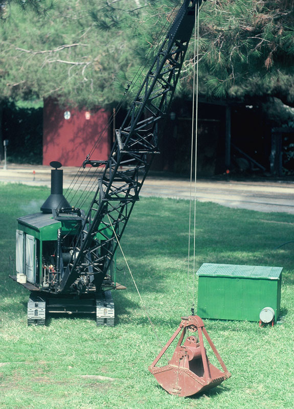
Finished Crane
The completed machine in use while still looking relatively new.
Finished Crane
Finished Crane
Finished Crane
Finished Crane
Finished Crane
Finished Crane
Finished Crane
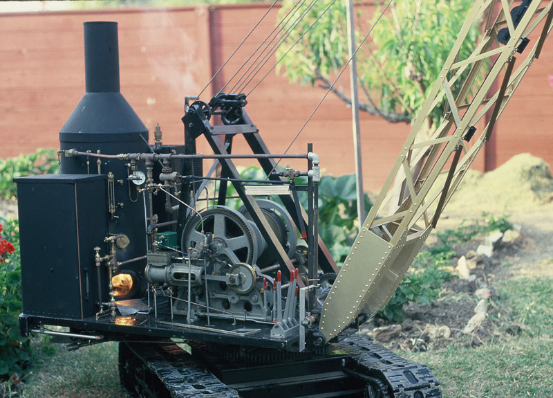
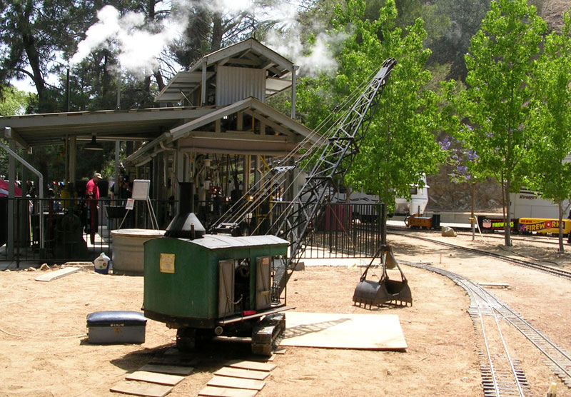
First Steam-Up
This photo shows the crane just after completion for the first steam-up!
Finished Crane
Notice how pristine the crane is at this point, before years of well-earned wear.
Finished Crane
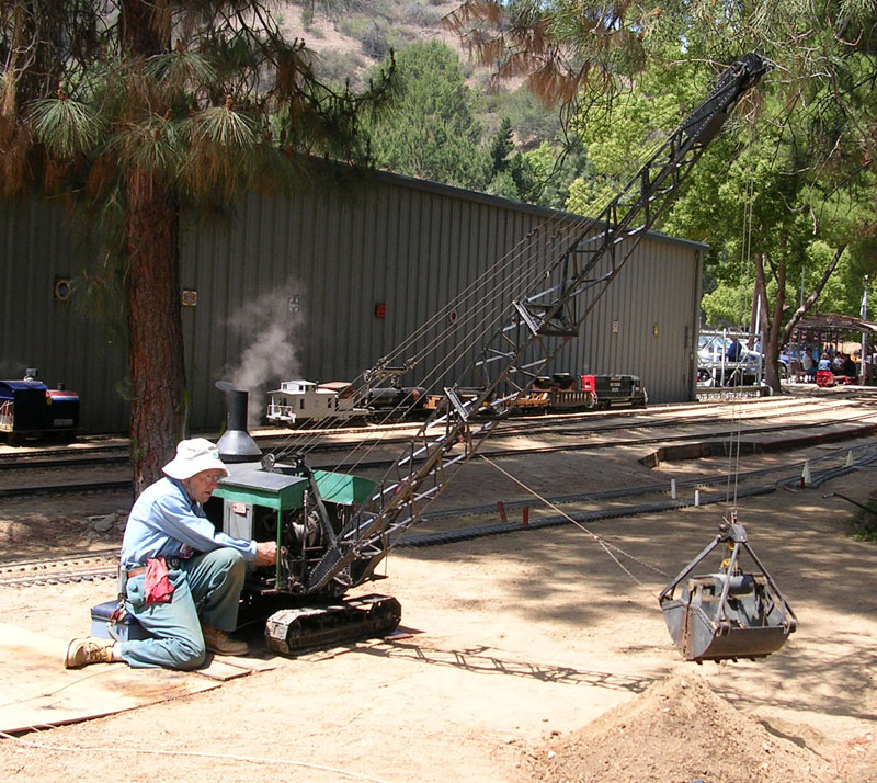
Jerry Working the Crane
Jerry Brown puts the crane to work at the LA Live Steamers steam club meet on Memorial Day weekend in 2007. Photo courtesy of Bruce Ward.
Finished Crane
After over 30 years of use, the crane was still fully functional.
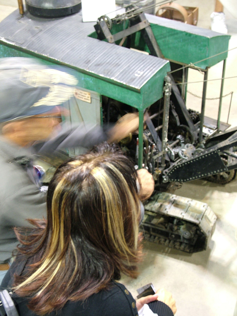
Jerry Demonstrating the Crane
This photo was taken at the 2005 show held in Visalia, CA. Jerry was there operating his steam shovel, and can be seen working on it while a spectator looks on.