Below you can view more photos from Mr. Dahlberg’s Mercer build, along with some other projects. Click on images to enlarge.
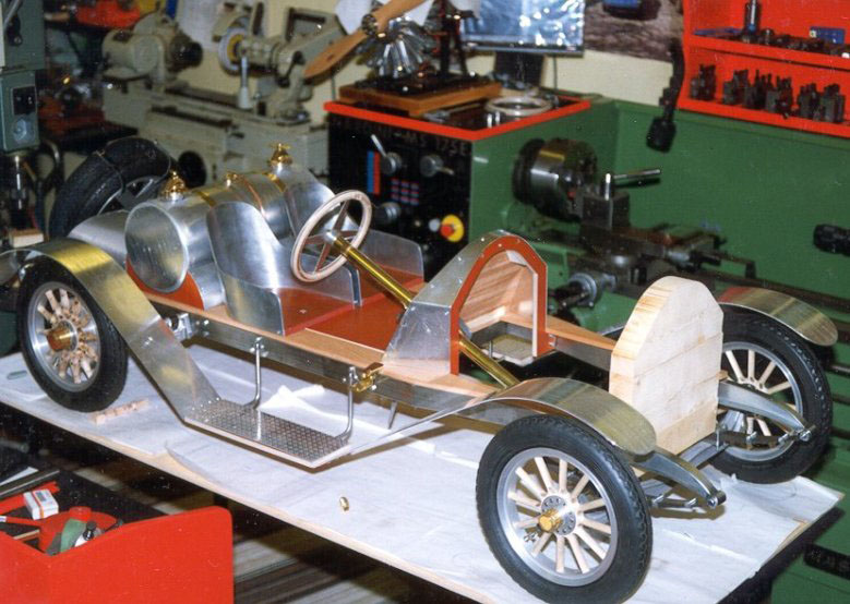
Scale Model 1910 Mercer T35 Raceabout
Wheel Construction
Since he started by purchasing the six tires, Ingvar decided to build the wheels first. He made a pattern, and cast the six rims in light alloy.
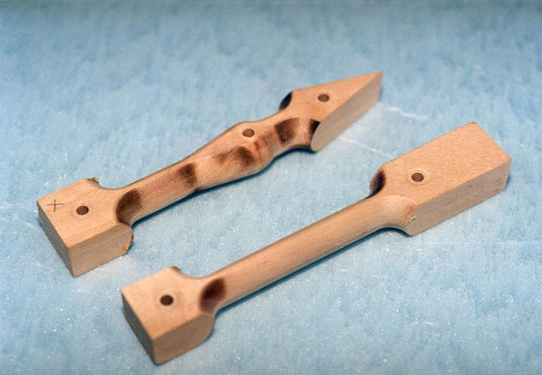
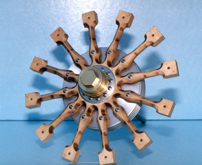
Wooden Spokes
The wooden spokes seen here were made from birch wood. Because the Mercer has no front brakes, the spokes are different on front and rear wheels. The spokes were made using a radius mill on a rotary table.
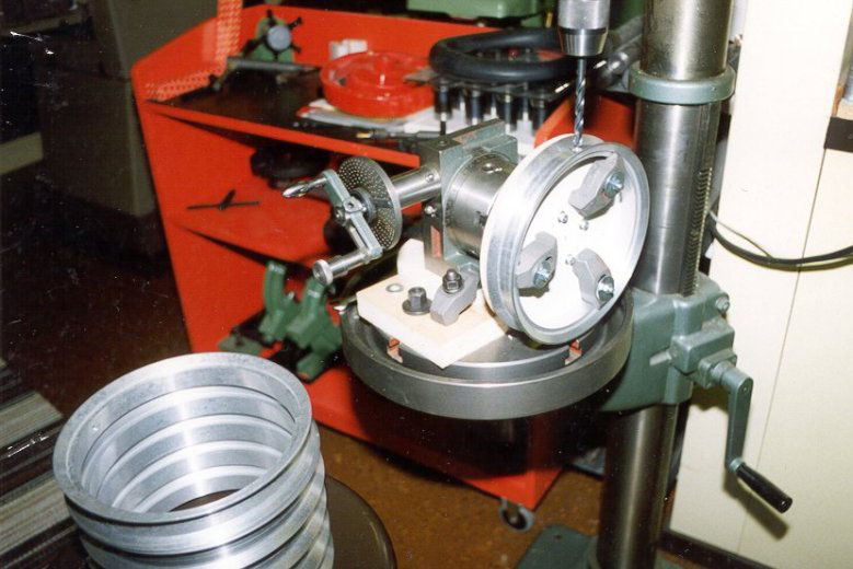
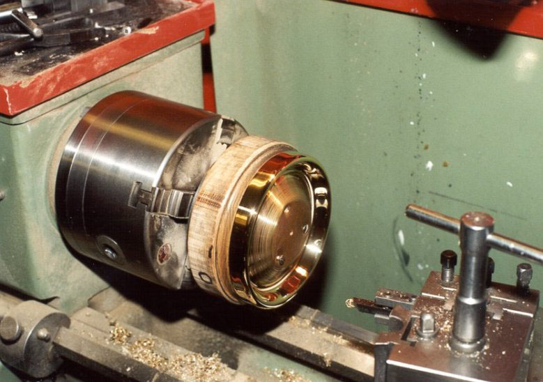
Rim Drilling
This photo shows the wheel rims being drilled for the spokes.
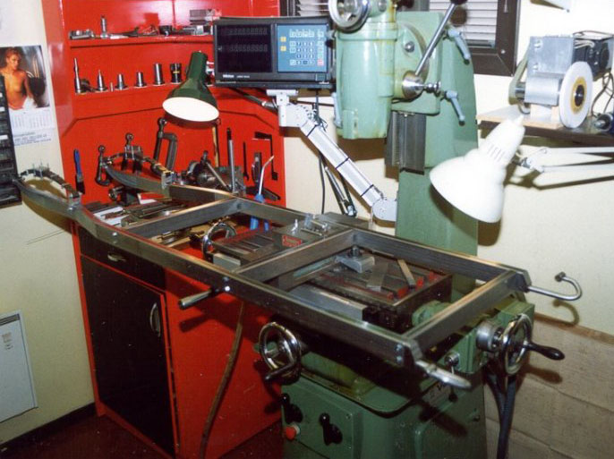
Milling the Front Axle
The axle has been cast from light alloy. Notice the completed front spring sitting on the right side of the table.
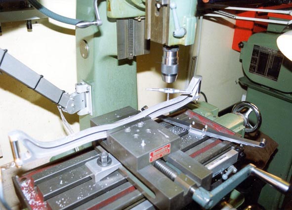
Milling the Frame
The frame is made from 20 mm x 40 mm steel tubing. The forward part was hammered over a 20 mm piece of profiled steel, and then welded to the front part of the frame. (Front springs have been assembled in this photo.)
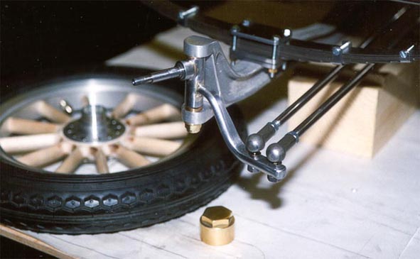
Front Axle
The completed front axle with spring, steering arm, and spindle.
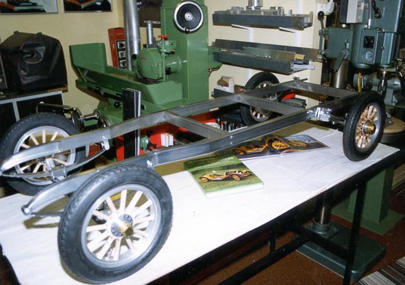
Front and Rear Axles
Front and rear axles are in place, and the frame sits on its wheels and tires for the first time.
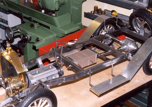
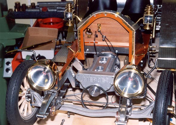
Frame Progression
The frame starts to receive other components, such as the radiator, rear axle banjo (differential), running boards, and rear fenders.
Frame Progression
More progress on the frame.
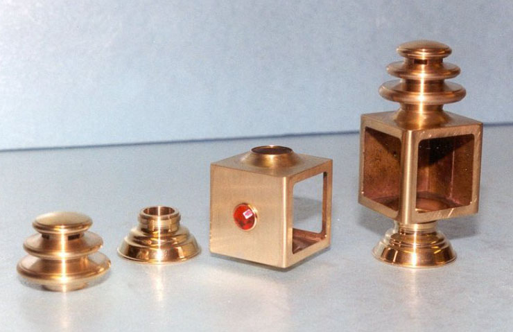
Brass Components
This photo shows some of the spun brass components, and an assembled side lamp.
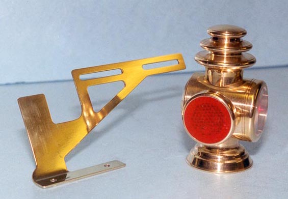
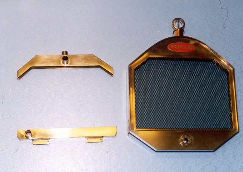
Brass Components
This photo shows the rear lamp and number plate holder—both made from brass.
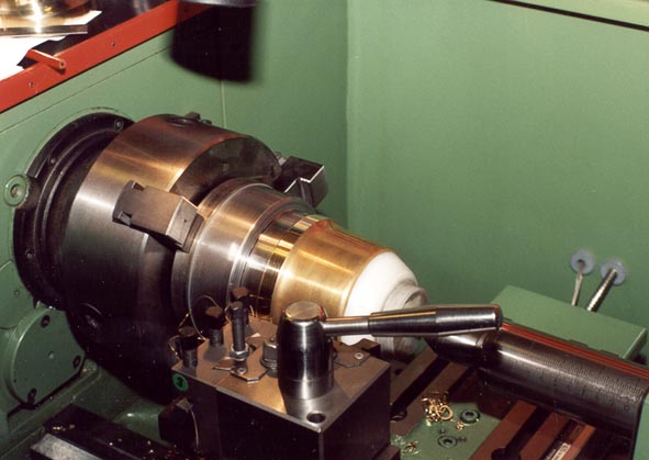
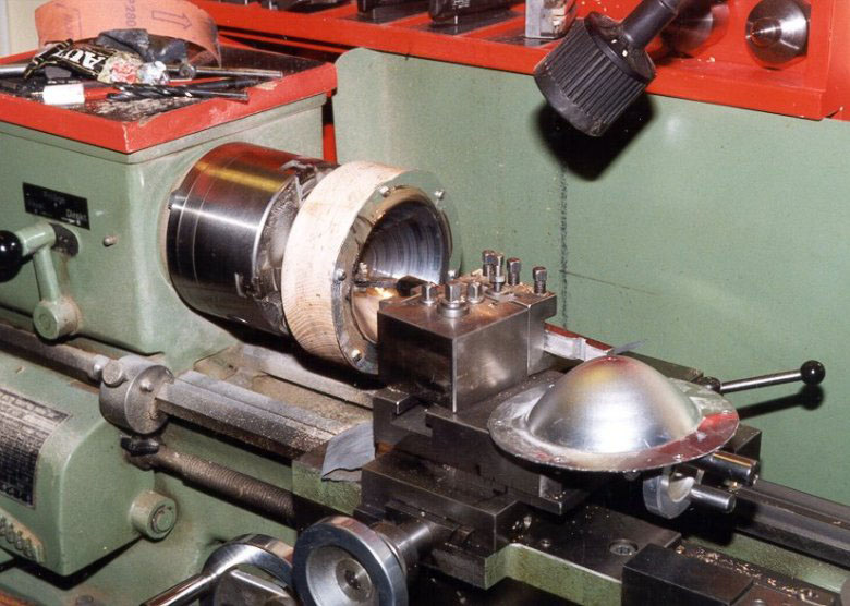
Form Turning
A heavy form was turned from metal, and then the headlamps were formed over it by the process of spinning. Turning the form generated about a wheelbarrow full of chips.
Form Turning
Spinning the 1.5 mm thick brass plate would work-harden it. The plate had to be heated several times to anneal it during the process.
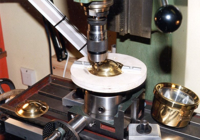
Headlamp Progress
This photo shows the headlamp rings and reflectors being spun.
Headlamp Progress
Final headlight assembly.
Radiator Frame
The radiator frame and tanks are made from brass.
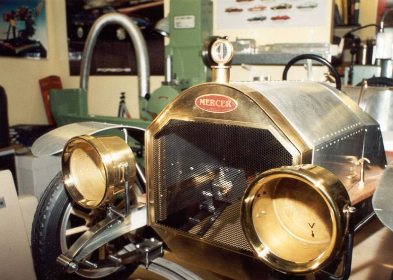
Front End Progress
In this photo, the brass headlamps and radiator have been attached to the front of the Mercer.
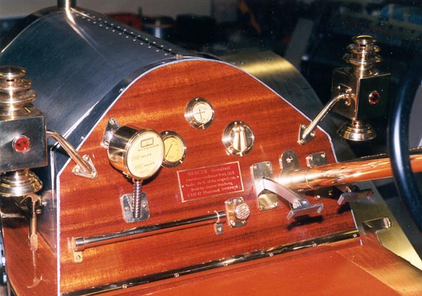
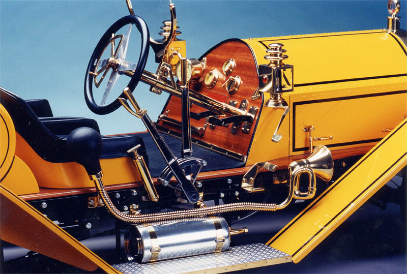
The Mercer Dash
The mahogany plywood dash is fitted with instruments (although they are non-functional). The instrument faces were drawn full-size, and then reduced in a photo copier.
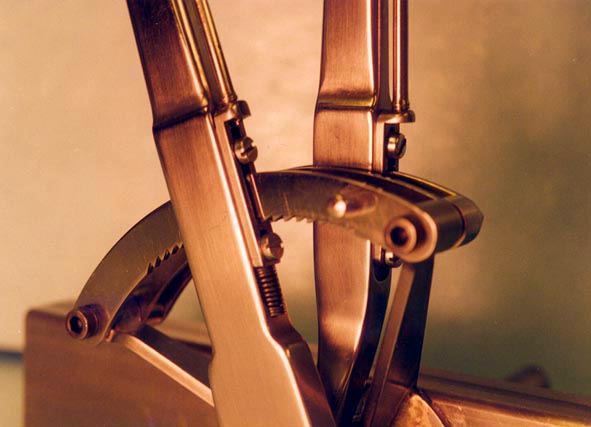
Handbrake and Gear Lever
This photo shows details of the handbrake and gear lever mechanism.
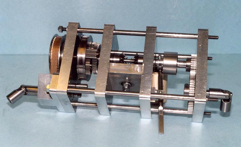
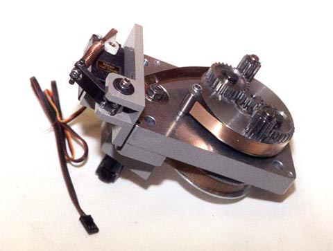
The Gearbox
The gearbox was designed to use a radio control servo, which operates the forward and reverse mechanism. Only one ratio was used, as the car was only operated at slow speed.
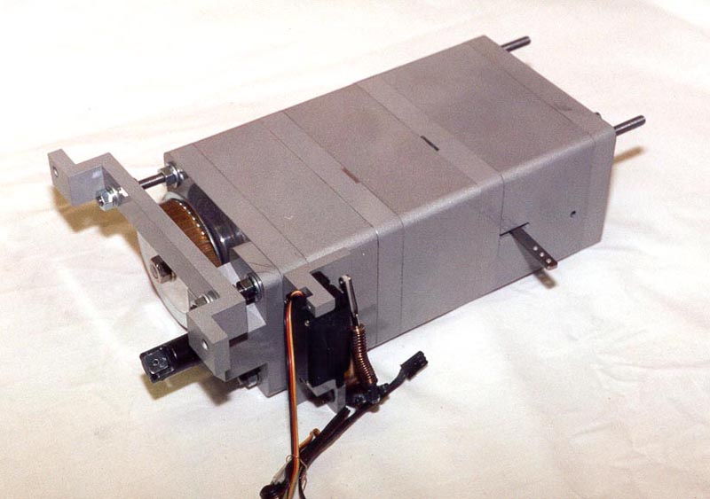
Finished Gearbox
The finished gearbox with cover in place.
The Clutch
The clutch utilizes a strip of phosphor-bronze wrapped around a wheel. This is operated by a landing gear servo. When stretched, the strip softly stops the wheel. Power from the engine is transferred to the forward/reverse part of the gearbox. The gear lever is operated by an ordinary servo motor mechanism.
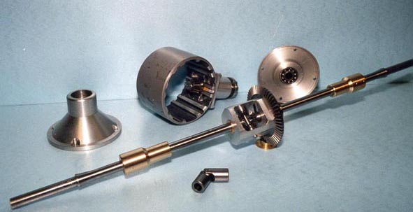
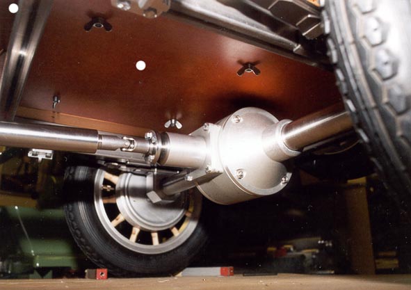
Differential Housing
The differential housing was made from part of an electric motor case found in a junk yard. The ends were turned from aluminum, and the axle bushings from bronze. The beveled gears were purchased, rather than being handmade. Ingvar did not yet trust his gear cutting abilities for such a critical task.
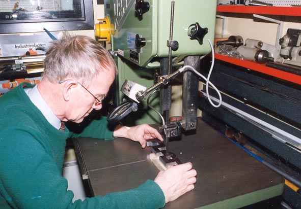
Ingvar Working on the Crankshaft
Crankshaft construction began by cutting a 10 kg (22 lb) piece of steel bar with the band saw. It was then surfaced with a fly cutter. The next step was to use a surface grinder from two 90 degree angles. Then after marking, it was returned to the bandsaw.
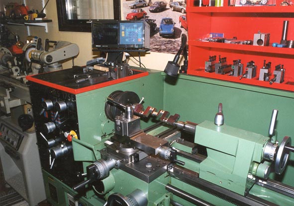
Crankshaft Construction
The journals of the crankshaft are turned in the lathe.
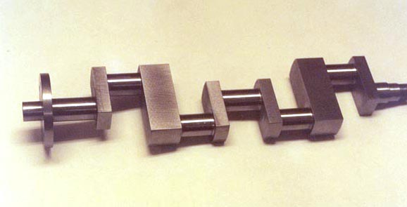
Finished Crankshaft
What started as a 10 kg billet ended up weighing just 800 grams.
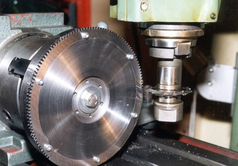
Flywheel Construction
Teeth for the starter gear are cut on the flywheel.
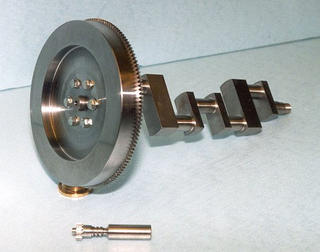
Flywheel and Crankshaft
This photo shows the massive flywheel installed on the end of the crankshaft.
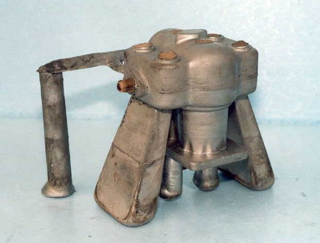
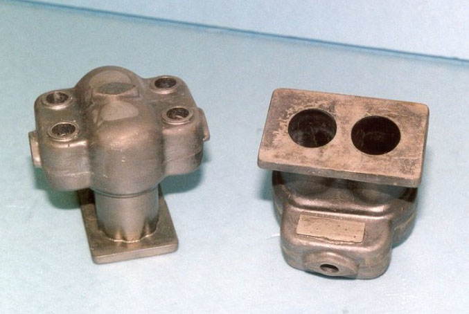
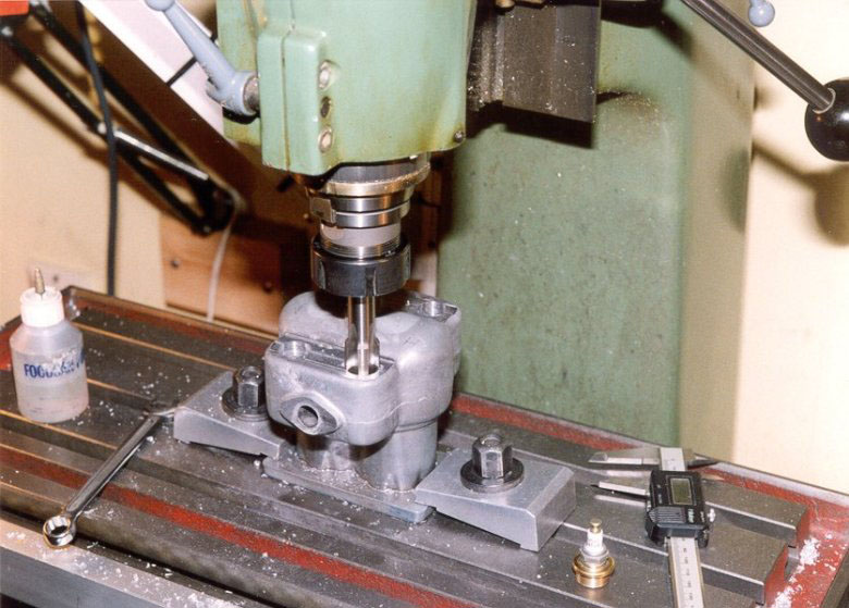
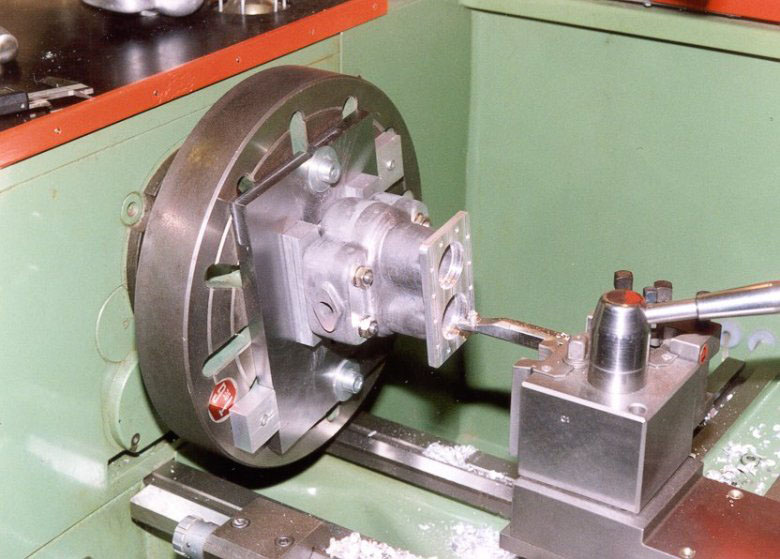
Crankcase Construction
Making the pattern for the crankcase was a unique job. Once cast, Ingvar could begin the process of milling them. The upper and lower crankcase halves were then assembled, along with the gear cover. Next they were attached to the ground baseplate on top of two parallel blocks, and fixed in the lathe. After arboring for the crankshaft, Ingvar then fixed the gearcover, and arbored the front bearing seat. The upper two parallel blocks were then removed so he could bore holes for the camshafts. In this photo, holes are being bored for the distributor.
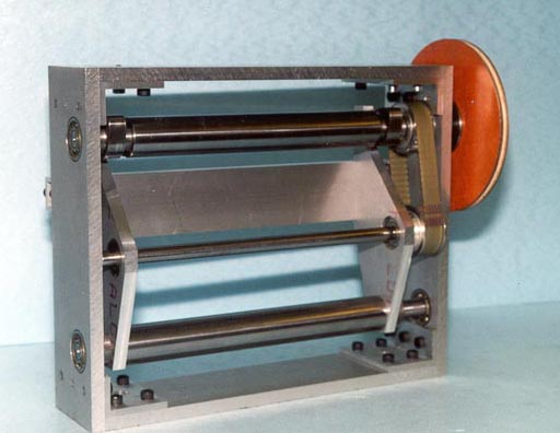
Camshaft Construction
Instruction from Strictly IC magazine led to the construction of a camshaft grinder. Ingvar attached it to his tool grinder, and made the camshafts from SIS 2940-03 steel. This is a standard Swedish material made for nitro-carbonization, which allowed the camshafts to harden without distortion.
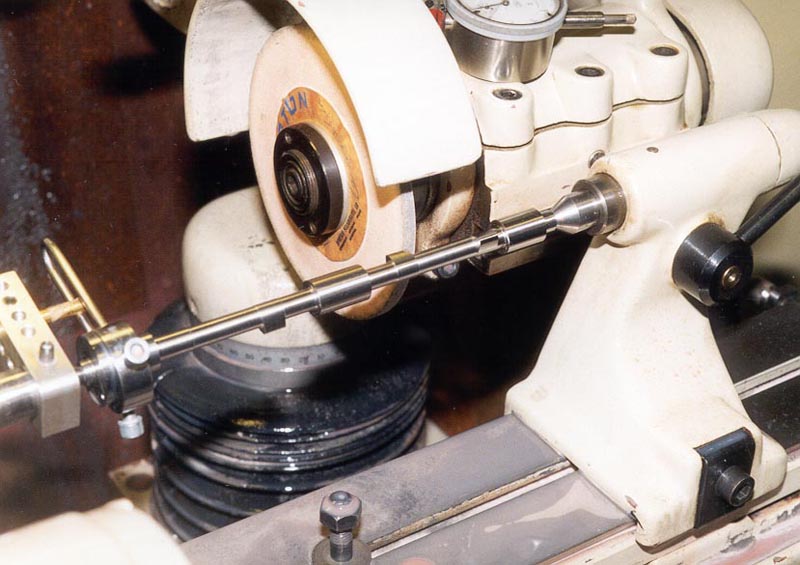
Grinding a Camshaft
A camshaft grinding operation is underway. The engine required two camshafts, but Ingvar made a third for display alongside the finished car.
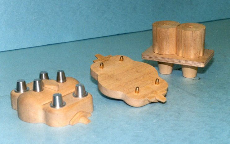
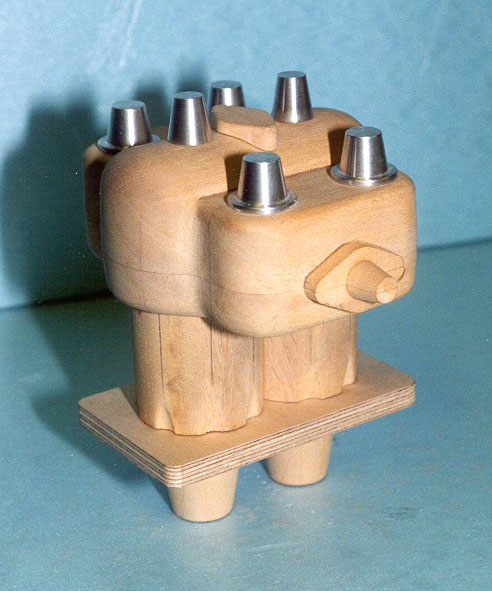
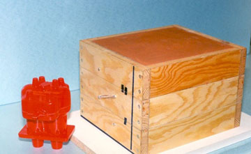
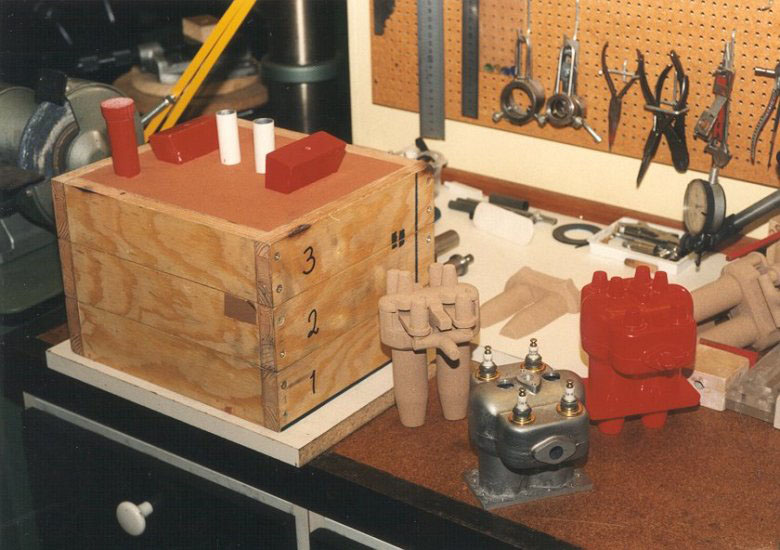
Casting Cylinders
Ingvar noted that it took one full year to get from the first patterns you see here, to the finished, machined cylinders.
Casting Cylinders
Casting Cylinders
Casting Cylinders
Casting Cylinders
Casting Cylinders
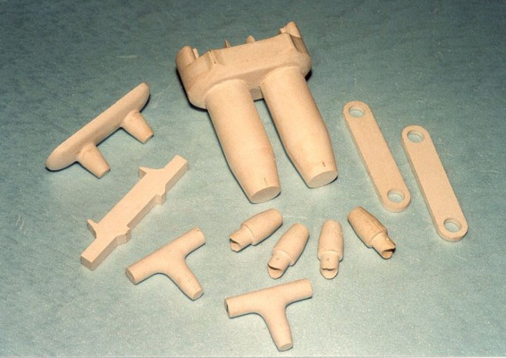
Once the cylinders were cast in metal, the sprues were trimmed off, and the part was ready for machining.
Casting Cylinders
Castings after machining.
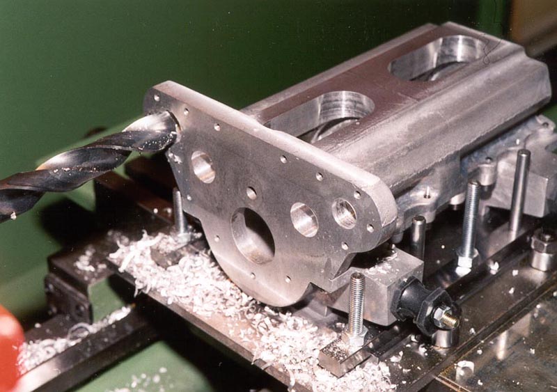
Boring the Cylinder Casting
Holes in the cylinder casting are being bored on the mill.
Boring the Cylinder Casting
Holes in the casting being bored on the lathe.
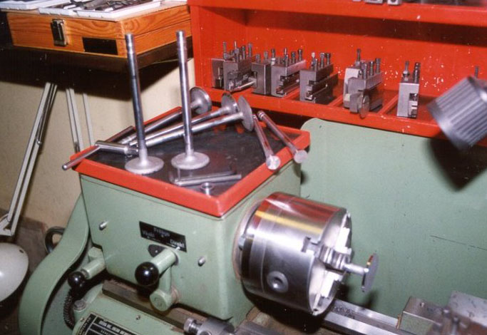
Turning Valves
Ingvar machined his valves from larger preexisting ones, so he knew he was working with the right metal. Pictured here are the original valves from a tank engine that Ingvar started with.
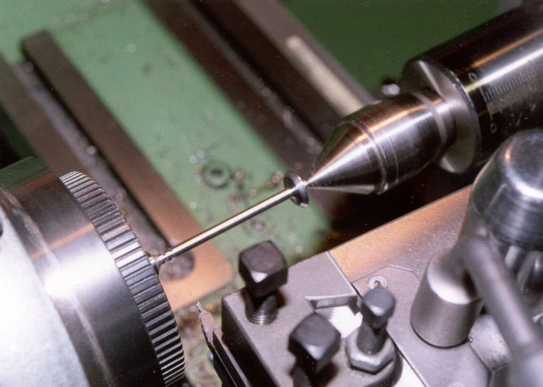
Turning Valves
Here is a Mercer valve being turned from one of the larger valves.
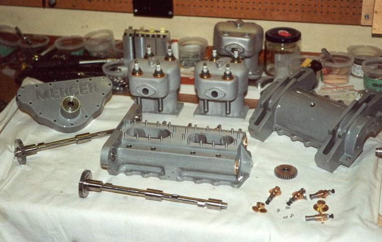
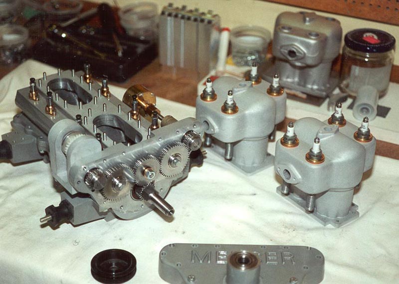
Engine Block Assembly
Engine components (with early distributor) prior to assembly.
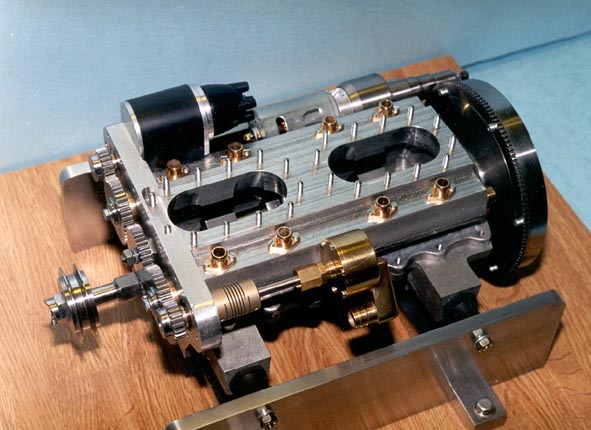
Engine Block Assembly
Block partially assembled.
Engine Block Assembly
The cylinders are ready to be bolted to the block.
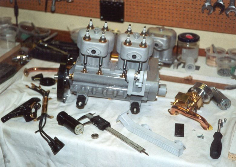
Engine Block Assembly
The engine block with cylinders attached.
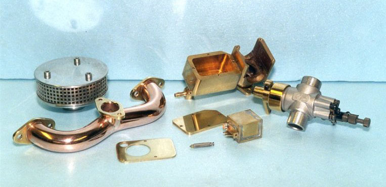
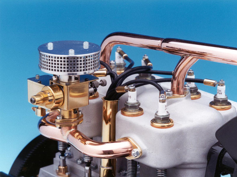
Engine Components
The intake manifold, carburetor, and air cleaner.
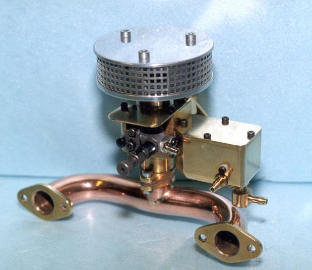
Engine Components
Intake manifold, carburetor, and air cleaner assembled.
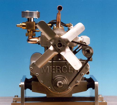
Finished Mercer Engine
The finished engine is shown from several angles.
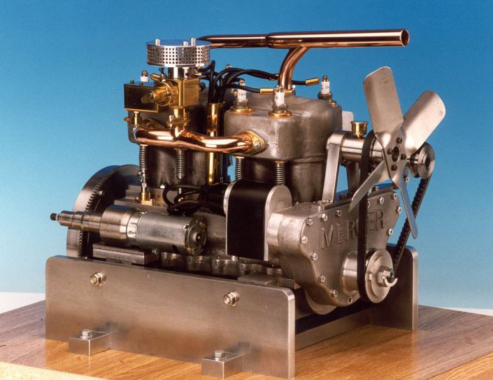
Finished Mercer Engine
The engine was first successfully test run in May, 2001.
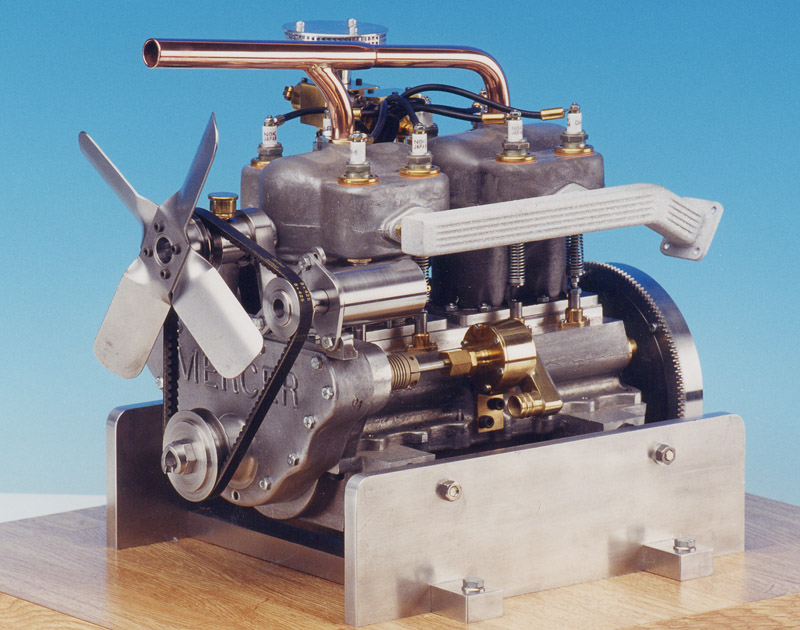
Finished Mercer Engine
Here you can see the original distributor, before it was modified for better performance.
Finished Mercer Engine
Rear Axle Assembly
The rear axle assembly is attached to the car, and wheels are in place.
Final Assembly
The Mercer is finally coming into form.
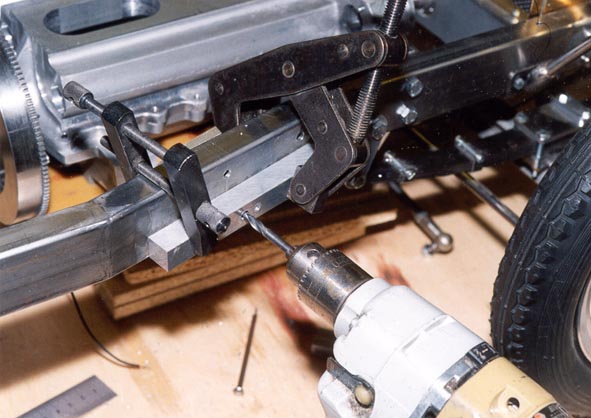
Final Assembly
Drilling holes for the engine mounting bracket.
Assembled Unpainted Mercer
The assembled car prior to painting. The raw metal body parts were taken to a plating facility, and given an electroplated finish for protection. The parts were processed alongside production Volvo parts for a modern car, which made for an interesting contrast.
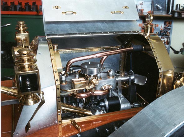
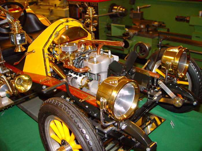
Engine Compartment Before Painting
The engine compartment before the bodywork was painted.
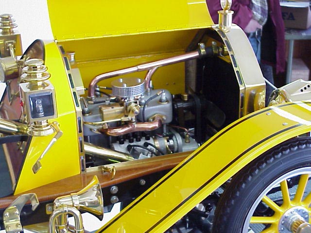
Engine Compartment After Painting
Note the difference between the early distributor design in the unpainted photo, and the more sophisticated double-magnet version that ended up being the final mechanism, shown here.
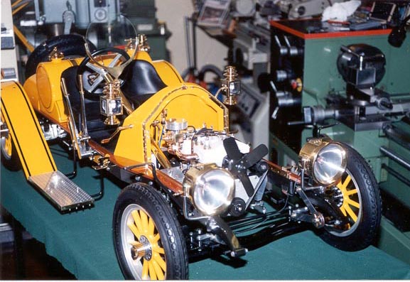
Final Assembly
Each part was disassembled and painted using automotive quality paint in a professional, dust-free spray booth.
Final Assembly
Final Assembly
More details from the final assembly.
Final Assembly
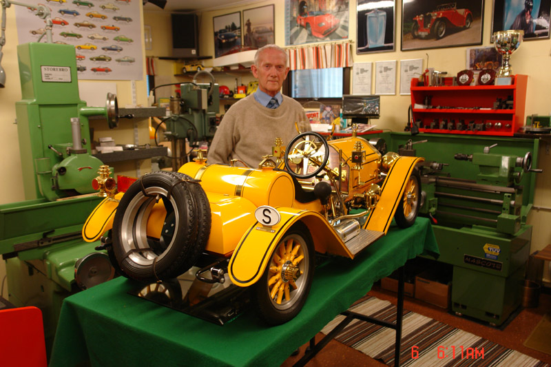
Mr. Dahlberg With His Finished Mercer
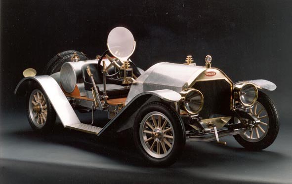
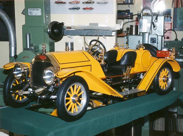
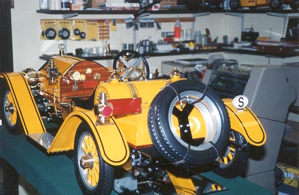
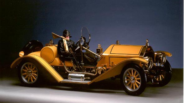
Completed 1910 Mercer T35 Raceabout
The finished car looks ready to drive!
Ingvar in His 1910 Mercer T35 Raceabout
Professional photographer Stefan Svensson composed this photo. He composed this picture using two separate photos: one photo of the model, and the other was a photo of Ingvar dressed in vintage driving gear with his scarf blowing in the wind. The images were blended in Photoshop, with Ingvar’s foot on the throttle, and hand on the steering wheel. Now we all know what it would look like to see Ingvar actually behind the wheel of his miniature Mercer—the perfect conclusion to his 5-year dream.
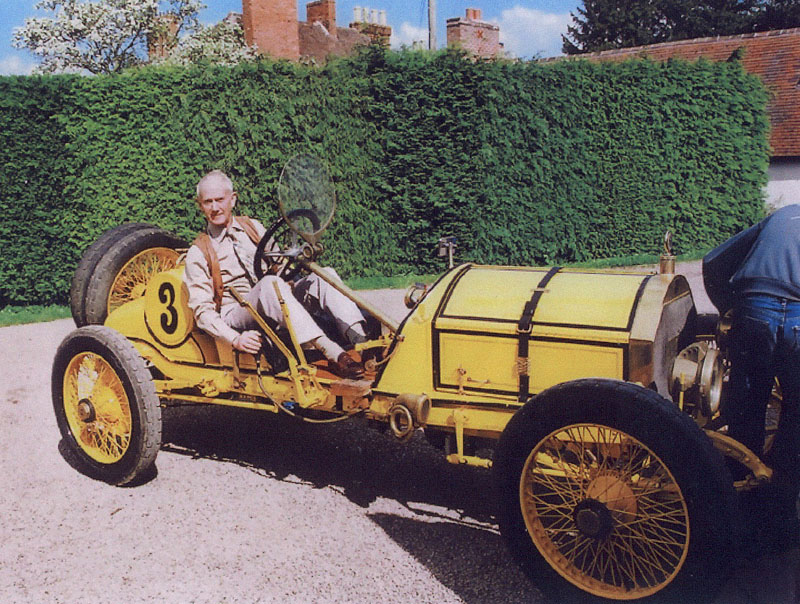
Ingvar in a Real Mercer
This photo, however, was not edited. Ingvar finally got to take a ride in a real Mercer several years after building his model.
Other Projects
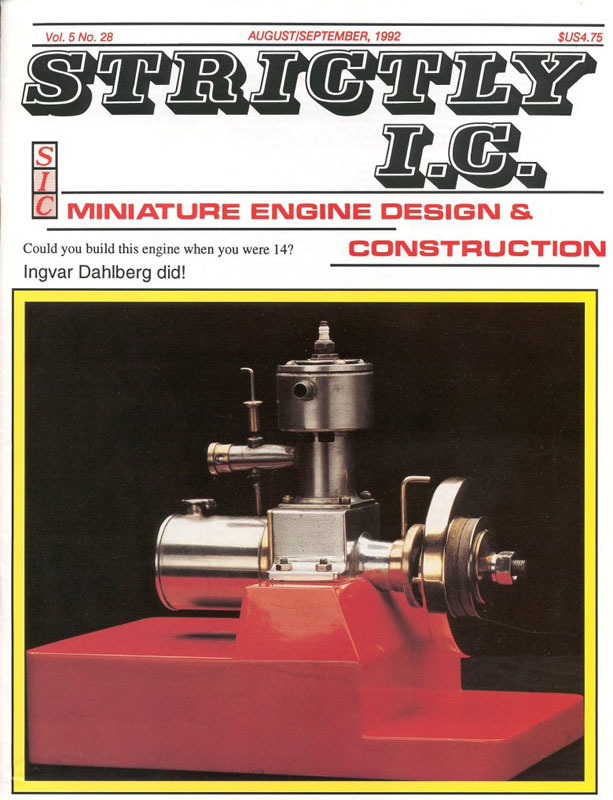
Early Engine
Ingvar got off to a good start early on, building this engine at age 14. It made the cover of the Aug/Sept 1992 issue of Strictly IC magazine!
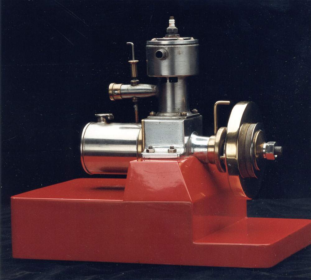
Early Engine
Regarding the engine, Ingvar said, “I was just 14 years old when I built this 14.3 cc two-stroke engine. It was made with simple methods. The crank-case was cast in a flowerpot with sand. The pattern was as simple as possible. Light-metal from discarded pistons were melted with the aid of a gas-burner, and poured into the mould. The petrol tank was made of a nickel-plated baking powder pot. The engine used to be equipped with a standard contact breaker, a 3/8″ spark-plug, and a standard coil for full-size cars. Nowadays, the engine is run with a glow-plug. All my pupils during 40 years of teaching Physics have seen it run on the teacher’s desk when studying IC-engines.”
Sea Lion Engine
This Sea Lion engine was designed by Edward T. Westbury, and built by Ingvar Dahlberg. It’s similar to the Seal engine built by the Foundation.
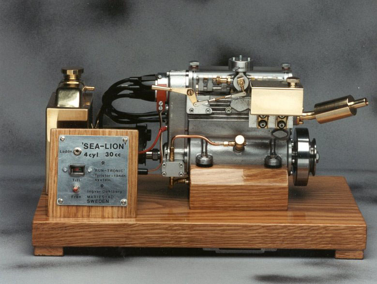
Sea Lion Engine
This model made the cover of Engineering in Miniature magazine in May, 1992.
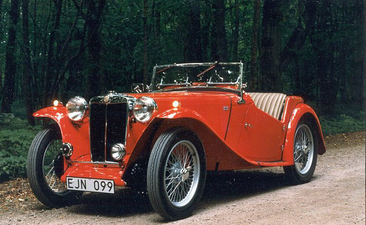
1949 MG-TC Restoration
The 1949 MG-TC that was restored by Ingvar and his son. The design of the post-war MG follows very basic automotive principles, and is not all that different from the 1910 Mercer in many respects.
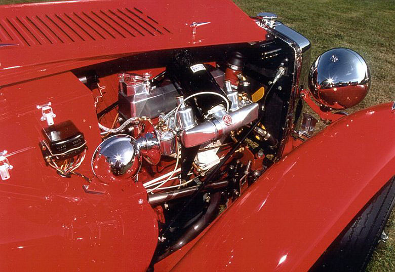
1949 MG-TC Restoration
Working on this car gave Ingvar the confidence to try building an entire car (in miniature) from scratch.
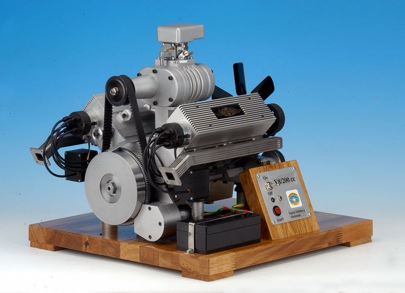
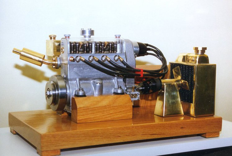
Supercharged V-8
This 200 cc supercharged V-8 was very close to completion when photographed here in January, 2005.
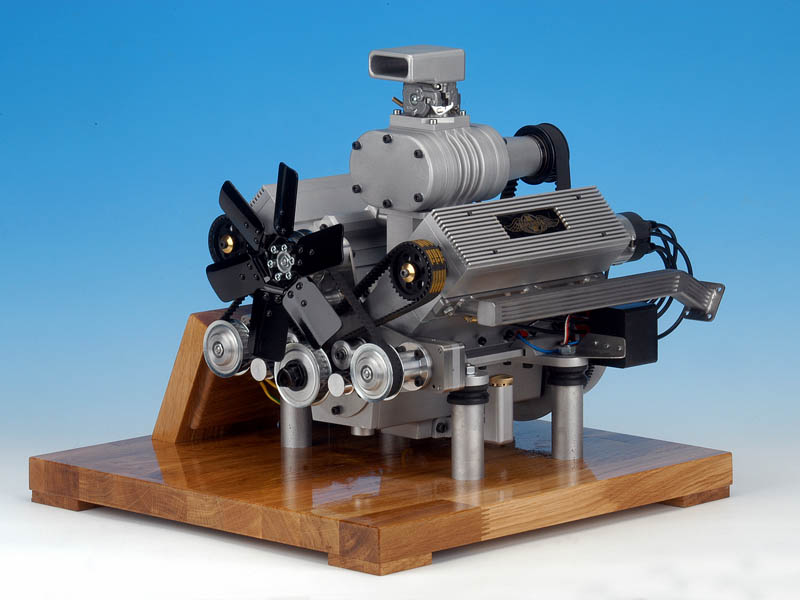
Supercharged V-8
This engine weighs just 25 kg (55 lb).
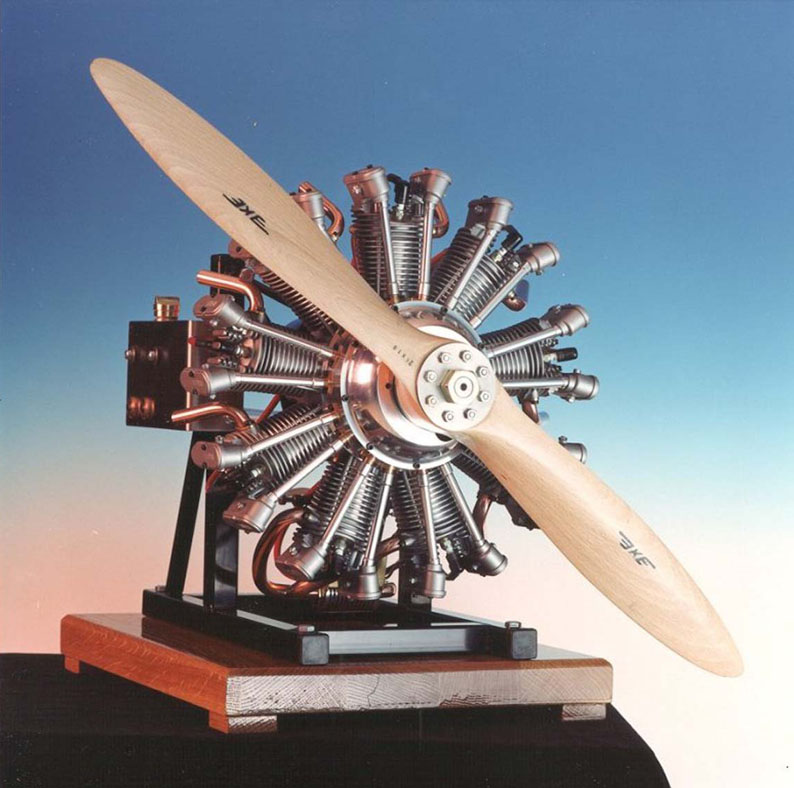
1/4 Scale Wright J5 9-Cylinder Engine
This 1/4 scale model of a Wright J5 9-cylinder aircraft engine displaces 130 cc. The model was designed by the late Karl-Erik Olsryd, and complete drawings have been published in the Swedish magazine Allt om Hobby, and the US magazine Strictly IC.
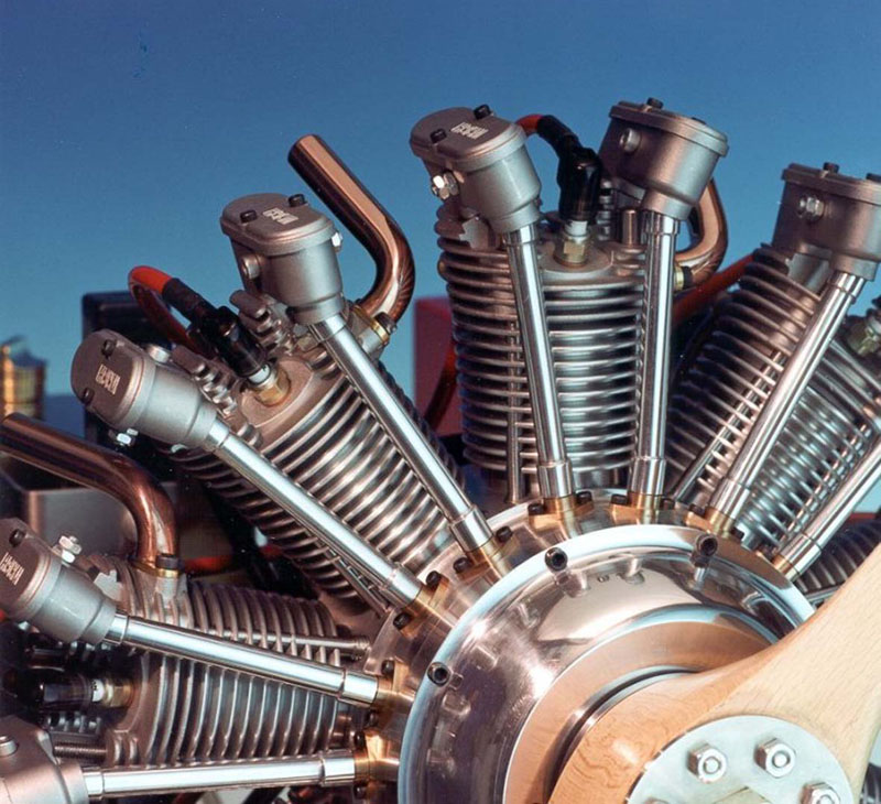
1/4 Scale Wright J5 9-Cylinder Engine
The cylinder heads were supplied by Karl-Erik. Casting sets and bearings were also available for those wishing to build this engine.