By Francisco Pulido
“In the 1920’s it was claimed that only two makes of car would race at Le Mans: one, a Bentley, and the other a representative from the rest of the world.”
The Great Magician
Walter Owen Bentley, better known as W.O., started to design and manufacture his famous sports cars after studying steam engines for a period of five years. So, in 1904, when he was sixteen years old, he began his training as a steam locomotive engineer. It was the fact of the steam engine being the machine which best demonstrated the balance between form, strength and speed which led to W.O.’s fascination with them. But perhaps the thing which excited him most was the speed, and so he dedicated his free time to competing in car races. He competed against Rex and Indian, and his sporting experiences include twice entering the Isle of Man Tourist Trophy, which comprised of pure speed tests, hill climbs, and velodrome races—including some at Brooklands.
In 1910, the 22 year old engineer stopped working with locomotives and spent two years on the technical supervision of several hundred taxis, including their repair and maintenance, at the National Cab Company in London.
In 1912, together with his brother, Bentley became the London Agent for the French development company DFP (Doriot, Flandrian & Parant). This factory, which was only six years old, entered its own cars in competition for the first time ever under Bentley. This agile 2 litre tetracylindrical engine was prepared for competition by the Bentley brothers. In this first competition outing, W.O. surprised the owners of DFP as much as the competition with a victory at the legendary Brooklands velodrome.
A short time afterward, he achieved the world speed record for a 2 litre engine with a velocity of almost 150km/h. The secret of his success was as a result of, amongst other things, his use of aluminum pistons. At that time, the durability problems had not been solved, and it was in this field that W.O. was a pioneer.
With the start of the first World War in 1914, Bentley founded the first British firm to make aviation engines which used aluminum pistons: the air-cooled Bentley BR1 and BR2, which had star cylinders. This resulted in them being among the best and most powerful in the allied forces. In 1919, Bentley founded his own car company with the aim of manufacturing, “a fast car, a good car, the best of its kind.”
The first car with a three litre engine was completed in 1919, and a month later he sent that car to the Olympia Motor Show. Orders started coming in, and a few months after that, he carried out his first road test; news of which was published by The Autocar. After this even more orders came in, and a small factory was founded in Oxgate Lane, Cricklewood.
The first 3 litre Bentley, a coupe, was launched in September 1921. This model was manufactured until 1923, and, despite its high price, 1,619 cars were sold. Its basic characteristics, however, were maintained in all the Bentleys made at the Cricklewood factory, where they made cars with 3, 4.5, 6.5, and 8 litre engines.
From 1931, the only part of the original car remaining was the name and the Bentley grill. This meant it had a very short existence—twelve years full of expectation, glory and fame—and also constant financial problems.
W.O. Bentley had very clear technical ideas, but remained somewhat confused regarding company matters. In the end, Rolls-Royce took over Bentley, and Cricklewood closed its doors forever.
Walter Owen Bentley managed three more years at the service of the silver lady (Rolls Royce). After that, he worked for Lagonda and Aston Martin, who he led to occupy the first three places in the 24 hours at Le Mans with 3 litre engines in 1954. That brought back memories of Bentley’s five victories in 1924, 1927, 1928, 1929 and 1930.
Those were the glory years during which the Bentley Boys achieved success for W.O. All the while, Ettore Bugatti ironically yet respectfully said that, “Monsieur Bentley made the fastest lorries,” due to the size of the cars.
W.O. lived until 1972. However, for his admirers who still preserve, care for, and drive more than a third of the 3,034 cars manufactured in Cricklewood, he was then and remains now unforgettable.
The Five Victories at Le Mans
When the organizers of the car marathon at the La Sarthe circuit invited W.O. Bentley to participate, he declined. Bentley claimed that his pure-blooded cars weren’t built to race for an entire day and night. Later, when he realized that there would be nobody flying the flag for Britain, he reconsidered and decided to race.
The race, with W.O. in charge of the team, didn’t turn out very well. The driver and official test driver, Duff and Clement, managed to hold onto the lead for a while. However, halfway through the race, a stone punctured the fuel tank. Duff ran 5 kilometers to get to the boxes, and Clement, on a borrowed bicycle and with 2 cans of fuel loaded onto his shoulders, made it to where the car had stopped. They managed to restart it. Despite these huge efforts, their rivals had gained a large advantage, and the Bentley had to settle for fourth place. The next year, in 1924, luck was with them a little more than the previous year, and the Duff-Clement combination made its mark on Le Mans. They covered over 150km more than the second placed team.
W.O. Bentley had already changed his opinion about the 24 Hours, and in 1925 he entered two cars: the usual Duff-Clement team, and a new team of Bertie Moir and David Benjafield. Racing with the convertible top up, Moir-Benjafield’s car consumed a lot more fuel than they had anticipated. The car stopped twenty kilometers from the official refuelling point. The other car practically took off and finished in second place.
Three Bentleys lined up for the 1926 race, including a new model—the Super Sport—which was lighter and faster. Twenty four hours of misfortune ensued: two cars ended up in two separate accidents, and the third retired twenty minutes from the end. The following year, W.O. Bentley added a very fast 4.5 litre car with the other two 3 litre cars. All the vehicles were equipped with a device which allowed the driver to regulate the brakes, as the brake shoes wore out.
During the first few hours of the night, a multiple accident almost eliminated all three Bentleys. They were all damaged; two irreparably. But the third, with a bent chassis, damaged steering, and almost without brakes, carried on with the race. Benjafield and Davis succeeded in hauling the damaged car to victory.
In 1928, more names were added to Bentley’s list of pilots: Birkin, Barnato and Chassagne. Nine minutes from the end of the race, Barnato, who was in the lead, realized that there wasn’t much water left in his radiator. Despite the high risk of the engine seizing up, he carried on and secured a third victory for Bentley at Le Mans.
1929 was a good year for Bentley: they entered five cars of which four occupied the first four places at the end of the 24 hour race. For the last three hundred kilometers, the Bentleys maintained their respective places and crossed the finishing line in a triumphant file.
Before starting the 8th edition of the 24 Hours Le Mans race, expectations were high for the 7 litre Mercedes compressor, driven by Rudi Caracciola and Christian Werner. W.O. Bentley rose to the challenge and entered two teams: one ‘official’ team, comprising three new 6.5 litre Bentleys, and one ‘private’ team comprising three 4.5 litre supercharged engines. As expected, the Mercedes took the lead from the start, but the Bentley drivers launched a ruthless attack to force the German team to use their compressor. W.O. had previously stated that the Mercedes wouldn’t be able to cope if it was obliged to race for a long time with the compressor connected. He was right, and the two Bentleys finished in first and second place. The fifth victory at Le Mans was the kiss of death for the London company. The huge economic crisis did the rest, and Bentley disappeared forever.
The 4.5 Litre With Supercharger (or “Blower”)
The famous race driver Sir Henry Birkin, together with Clive Gallop and the expert in supercharged compressors, Amherst Villiers, developed a supercharged version of the 4.5 litre Bentley. It was much faster than the conventional 6.5 litre cars. This decision was made against W.O. Bentley’s will. He was somewhat wary and didn’t really trust the engines, although while they lasted, their speed was incomparable. Proof of this is Birkin’s still standing record at the former Le Mans circuit.
Birkin also achieved another record at the Brooklands circuit, when he convinced the Honourable Dorothy Padget to finance their participation. With her support, he built a car which is often referred to as the Auto Pau. With this car Sir Henry reached 220 km/h during the Grand Prix in Pau, and finished in second place with an average of 143 km/h throughout the 395 km race.
Technical Description
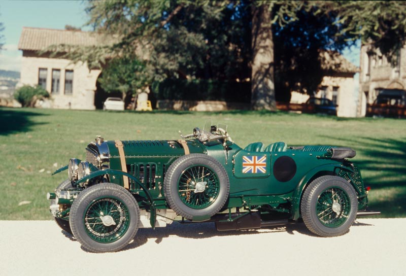
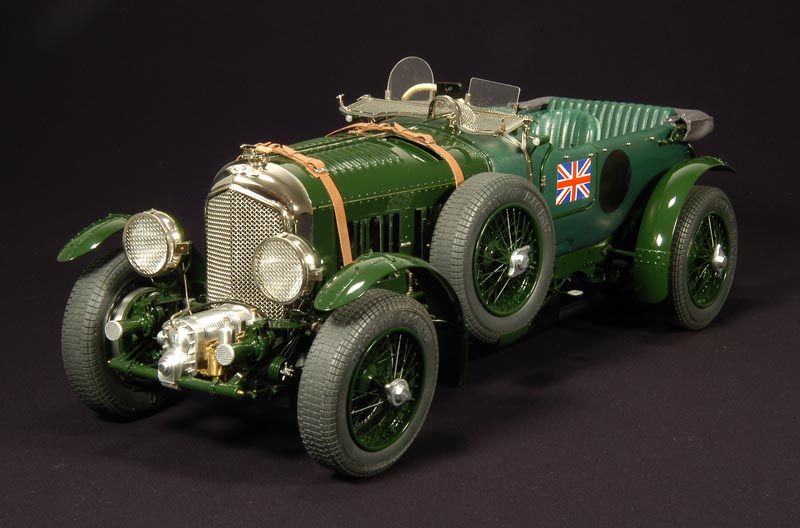
Model—4.5 Litre Supercharged Bentley, 1930
Engine
Regulation: front longitudinal
Type: four linear cylinders, water cooled
Cubic Capacity: 4.398 cc
Diameter x Stroke: 100 mm x 140 mm
Compression ratio: 5:1
Distribution: four sloping valves per cylinder controlled by one overhead camshaft on a vertical axle from the crankshaft.
Fuel Supply: two SU carburetors and a Roots type Amherst Villiers compressor.
Ignition: two magnetos and a coil
Maximum Power: 240 CV at 2.400 rpm (compressor) 175 CV at 3.500 rpm (series car)
Transmission
Regulation: gearbox following the engine. Rear-wheel drive
Clutch: dry, one disc
Gearbox: 4-speed with manual change. 1st -2.66:1, 2nd -1.65:1, 3rd -1.35:1, 4th -1.00:1
Secondary Transmission: by shaft
Connection: 3:1
Suspension
Front: rigid steel axle with ‘H’ section, with semi-elliptical springs and shock absorbers.
Back: rigid axle with semi-elliptical springs and shock absorbers.
Steering, Brakes, Wheels, and Tires
Steering: worm gear
Brakes: drums on front and back
Wheels and Tires: spoked Rudge Whitworth wheels with 6” x 15” Dunlop tires
Chassis and Bodywork
Type: high-resistance steel chassis with open bodywork. Two-seater sports car
Dimensions and Weight
Length: 4.381 mm
Width: 1.740 mm
Wheelbase: 3.300 m
Weight: (unloaded) 1,921 kg
Performance
Maximum Speed: 200 km/h
Fuel Consumption: 28 litres/100km
The Scale Model
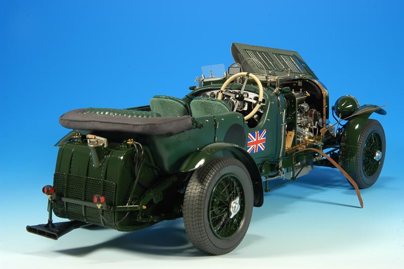
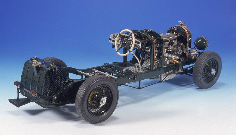
I started making this model with the challenge of improving on my previous model, the Bugatti Type 59. In reality, the Bentley is a very demanding car for a model maker, due to the fact that many of the mechanisms are on display—so they have to be perfect. Once again, I decided to work to a scale of 1/10, as this size allows maximum detail and enables me to make all the mechanical parts, including authentic screws myself.
The key to success was an endless supply of patience and consistency, as it took me more than three thousand hours to make and assemble the almost six thousand pieces which make up the model. As a journalist once said, “the patience to the service of the art.”
Documentation
From the outset, I had to assemble good graphical documentation based on various articles from different magazines and specialist books about the Bentley. I realized straight away that, despite having all this information, there still wasn’t enough to enable me to achieve the quality of workmanship that I desired. Therefore, I carried on investigating until I found a Bentley 4.5 litre in the Antic Car Club de Catalunya, whose President was the owner of the car. It wasn’t the supercharged version, but it served 80% of my needs.
The Antic Car and José Bascones , it’s President, very kindly made the car available to me to take photos and measurements from various angles. Moreover, at the Retromobile Fair in Paris, I came across a supercharged Bentley on display. Luckily, the owners let me take pictures and note down anything that would be of use to me. My friends, the couple, Phyllis and Gerald Wingrove also helped me with additional information.
The Wheels
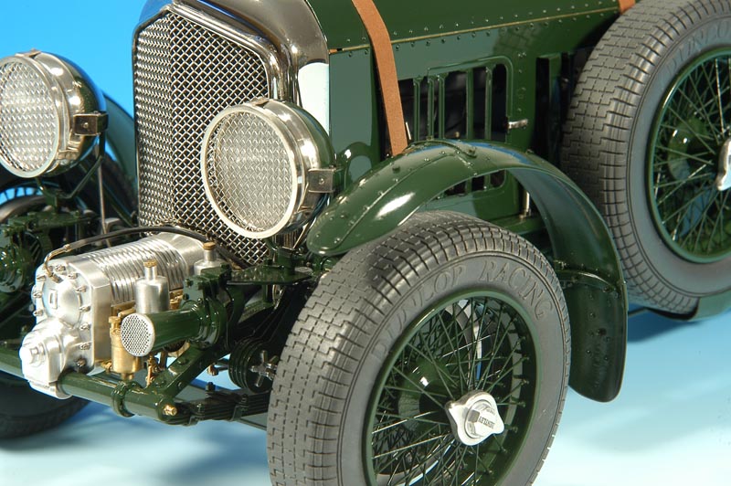
The wheels on the Bentley are Rudge Whitworth type, spoked with 6×15” Dunlop tyres. Making the wheels always requires special care, as they are a very visible part of the car which attracts your attention. The eighty spokes are mounted on two levels, and have to be exactly to scale, although this includes laminating the rod to make the spoke to scale. Each one has to be precise, as differences in thickness would make it inaccurate.
I started the process by planning all the steps for the framework of the spokes on paper. Then, I put a round piece of brass in the lathe to begin to reshape the rim. I repeated the same operation to make the different layers of the axle casing/housing. I used brass for these pieces, as they would later be painted in British Racing Green, like on the original model. In addition, I had to draw all the holes on the rims and axle holes on templates on adhesive paper. In total I drilled 800 0.5 mm holes, and this required extra special care. I had to make a small bradawl master to make the small bulges in the rim where the spokes separate.
To make the actual spokes, I used steel tube with a diameter of 0.5 mm on the inside and 0.8 mm on the outside. For the heads, I made a small square on the tube using special pliers which I had prepared for this job. Once all the pieces had been prepared, the next thing I had to do was make a tool to help me assemble the spokes.
In this case, it was easier to paint all the pieces before assembling them, as trying to paint between eighty spokes would have been impossible. The only things left after this were the tyres. To make them I used a round piece of nylon, 80 mm in diameter, to make the master. Then I injected resin into them to make the actual tyres. The tyre valve is made up of two pieces: the neck and the lid. This was the last piece to be incorporated into the rim.
The Chassis
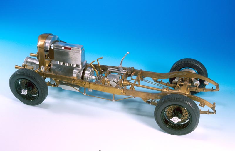
Like in the previous model, the chassis is made up of two longitudinal tie-beams, and three main crossbeams, which were then used to support the compressor, the engine, and the gearbox, as well as supporting other mechanisms.
The first difficulty I ran into was doing the scale drawing of the original model, given that it is a very long piece which has numerous curves. These all have to be perfect to achieve the desired effect, as this forms the skeleton of the car.
I used a brass handrail, and then I drew the profile of the chassis on the widest part, and the curves on the upper part of the handrail. After that, I fixed this piece with clamps to mill the curves of the tie-beams. Once this operation had been finished, I changed the position of the fixings to enable me to mill the definitive profile of the tie-beams. Then, when the upper part had been hollowed out, I was able to solder the crossbeams and the tips with silver. That completed what would be the backbone of the model.
Following on from that, I had to make the rest of the chassis pieces, including: the axles, the drums, springs, shock absorbers, transmitters, the compressor, the carburetor, the headlights, the radiator, the engine block, the clutch, the gearbox, the cardon joint, the differential, the petrol tank, the firewall, the dashboard, the exhaust pipe, the mudguard, and the bodywork.
For the moment I won’t go into detail about all those parts, and just deal with positioning them on the chassis.
Basically, I used brass to make the majority of these pieces. Brass is a very malleable material; it is easily machined with steel tools, it isn’t complicated to solder, and moreover, it is easy to drill, thread, and nickel-plate. Also, I decided to use aluminum for the parts where aluminum was employed on the real car.
Aluminum is not as easy to machine and additionally, drilling and threading is much more difficult and risky with aluminum than brass. Another disadvantage is that it is impossible to solder pieces of such small dimensions.
This model incorporates a wide range of screws, measuring 0.7, 0.8, 1.0, 1.2, and 1.4 mm. Moreover, hexagonal screws made by myself have also been used. This required great effort, but it was worth it in order to achieve the perfection that I was looking for. We’ll now move onto how I made all the previously mentioned pieces which were then incorporated into the chassis.
The front axle appears to be a simple piece, but it caused great difficulty. It is a rigid axle in ‘H’ form which, apart from milling the profile, has to be hollowed out from inside and shaped so it supports the springs. Other interesting parts are the ‘U’ shaped pieces which support the two front drums. They have to be milled at a 5 degree angle which is necessary for the front wheels.
To make the shock absorbers, I prepared a small master to cut the thirty equal pieces, which make them up from 0.3 mm sheet. Combined with the intermediate discs, the screws, and the regulation pieces, that finished off the shock absorbers.
The Compressor
The compressor is one of the brightest and most colourful parts of the car. It is an Amherst Villiers Roots, and attracts your attention due to it’s size at the back of the chassis. The head of the compressor required complicated milling due to the different circular parts that make it up. I also had to drill various holes to be able to hold the piece using 1 metric screws.
Following that, I made the body or central part, laterally milling it with an ‘H’ shaped tool to make the cooling fins. But also remembering to leave spaces in between for the pins which would hold the compressor head. The final part was a round piece which I made using a simple turning operation. After that, I made the finned outlet pipe that is fixed onto the left hand side of the compressor.
It comprises various pieces, which were all milled, turned, and fixed onto the side of the compressor using blind screws. On the right of the compressor are the variable diffuser carburetors made by the SU Company. All the pieces of the two carburetors were made from brass as on the real car, except for the vacuum chamber bells which I made from aluminum.
It was also necessary to produce two photo-etchings, with the make and the characteristics of the carburetors, which I positioned on the top of them. I had to also put a fine mark on the heads. The carburetors took me several days to build the 70+ pieces which make them up.
The Radiator
The radiator grill on the Bentley has a single form, specific to this make of car. I started to mill it from a piece of brass, taking into account that it would have to be finished by hand on a lime base, given that it doesn’t have consistently smooth curves. The upper part of the block is maximized to work on the body of the radiator.
The front grill is made of stainless steel, and it is important that it is to scale; the light spacing as much as the diameter of the grill. The top/lid is the most complicated part of the grill due to its reduced dimensions. I made it like the real one, so it could be opened and closed. The most challenging part was getting the pressure right for the closing mechanism.
The small top is made up of no less than seventeen pieces of brass, which were then nickel-plated. They all have to move perfectly, and one of the most difficult parts was making the two wooden handles on the upper piece.
To finish the radiator, I nickel-plated the grill, too. I chose this instead of chrome-plating it because at the time the Bentley was made, this type of chrome plating had still not been invented. One always has to take into account historical references if the desired objective is to produce a perfect model.
Lastly, I needed a new photograph with the Bentley emblem on it, which I later nickel-plated and positioned on the upper part of the grill. To finish, I had to create the hump where the water tube re-enters. In this hump I positioned the sensor which measures the temperature of the water.
The Gear Box
The gear box is separate from the engine, and is situated in the middle part of the chassis. There is a short transmission driveshaft from the engine to the gearbox back, and a second drive shaft with universal joints at each end from the rear of the gear box to the differential at the back axle. It is made almost entirely from aluminum—the only parts made from brass are the register heads. On the right hand side of the gear box you can see the transmission arm where the gear-change is situated.
A small box where the ‘H’ goes, comes from the gear-change lever, which I’d previously milled on 0.3 mm aluminum sheet, and which is attached with 0.8 mm screws. The gear-lever itself was simply made by milling, and then I attached an aluminum handle on the end. To finish, on the upper-central part of the gearbox I had to mill a small ventilation grill, which, due to it’s size, had to be fastened with 0.6 mm screws.
Petrol Tank
From the back you can really get a good view of it, and appreciate the size of the petrol tank. I used 0.8 mm brass sheet to make it, made into a strip and then formed, as on the real car. The mesh protection is in place because at that time the roads were generally gravel, and it was quite normal for stones to fly up off the road and puncture the petrol tanks.
In the upper part is the petrol filler and the petrol cap, which have the same pieces as the radiator but on a larger scale. The petrol pipes are located on either side of the tank, and have four taps to open and close the petrol flow.
The rear lights are mounted on a bracket right at the back, which is also used to support the end of the exhaust pipe. The rear lights were quite difficult. Firstly, I made a ball using the lathe, and milled three slots above which I put the red methacrylate circles for the lights. After that, I made a fourth hole where I soldered the bar which attaches the lights to the bracket. Then I made a fifth hole to attach the fitting where the cable which feeds the pilot lights goes in. The amount of work compared to the tiny size of the piece is incredible.
Steering
As I’ve previously mentioned, the steering is one of the things that requires the most care and attention when it comes to construction. It has a worm gear inside, and a pinion which transmits the movement to the wheels. It is made of aluminum, and was built entirely with the lathe.
The Firewall
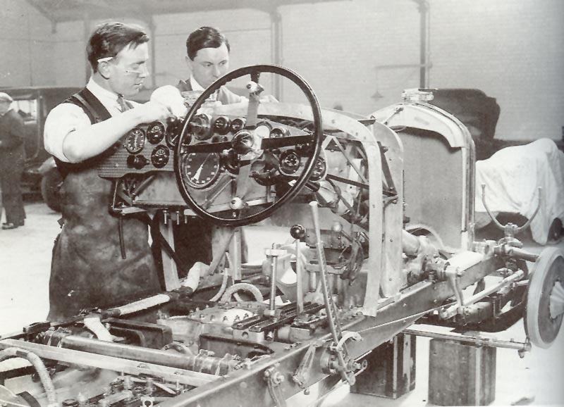
Due to the length of the bonnet and the fact that the engine has four cylinders, the firewall protrudes slightly compared to the bodywork, which adds to the car’s attractiveness. This means that it was necessary to detail the firewall on both sides. This protrusion of the firewall leaves the back of the dashboard exposed, meaning it was also necessary to detail it with precision, including the cables. The complexity of the firewall and dashboard meant that I spent more than six hundred hours on them.
Basically, it is made up of a mixture of 1, 3 and 6 mm brass sheets where I positioned the dynamo with its connection to the engine, the current regulator, two petrol tanks, angular supports for the dashboard, the accelerator, two connection boxes, and infinite connection pieces which go from one side of the firewall to the other—carrying pipes with oil, water and air.
All these auxiliary pieces were made from brass, and then either painted or nickel-plated, with the exception of the lid of the current regulator which was made from aluminum. The ignition boxes were made from ebonite, as on the real car. I had to be extremely meticulous due to the fact that tubes, flexes, cables, and other mechanisms pass across the firewall, and these are seen by the observer when they open the bonnet.
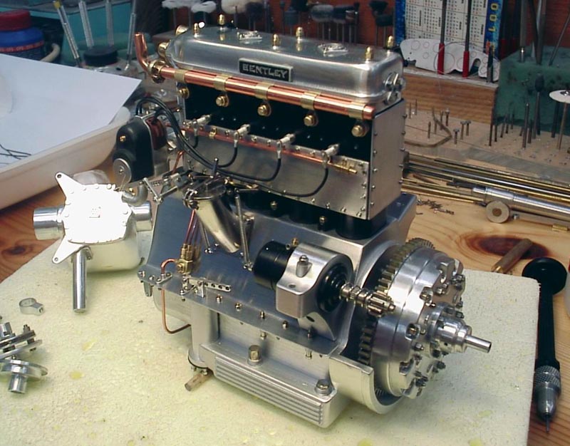
The Engine
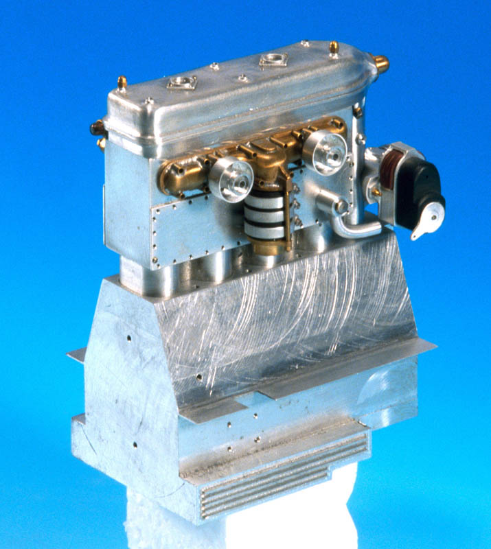
Like in the real model, I used aluminum to make the majority of the engine. As I said earlier, working with aluminum carries a great risk, due to the fact that it is much more durable than brass, and very common for drill bits and pins to break whilst drilling or threading.
The engine is made up of three main parts: the block, the cylinder, and the cylinder head or rocker lid. It is supported in the chassis by three points: at the front; the part where it connects with the compressor; and the two arms which separate the block, and rest on the tie-beams of the chassis.
The detail on the engine is a different matter altogether. You have to begin by making the largest pieces first, moving down to the smallest pieces last. Firstly, I milled the drive shaft and the arm which supports the two magnetos. the bodies of the magnetos were made from ebonite like on the real car, and the magneto insulation is made of bakelite.
Now, I’ll move on to the most complicated part of the whole model: the inlet manifold. It is made up of 87 pieces, of which 26 are soldered. Hopefully this gives an indication as to the difficulty involved in the making of this piece.
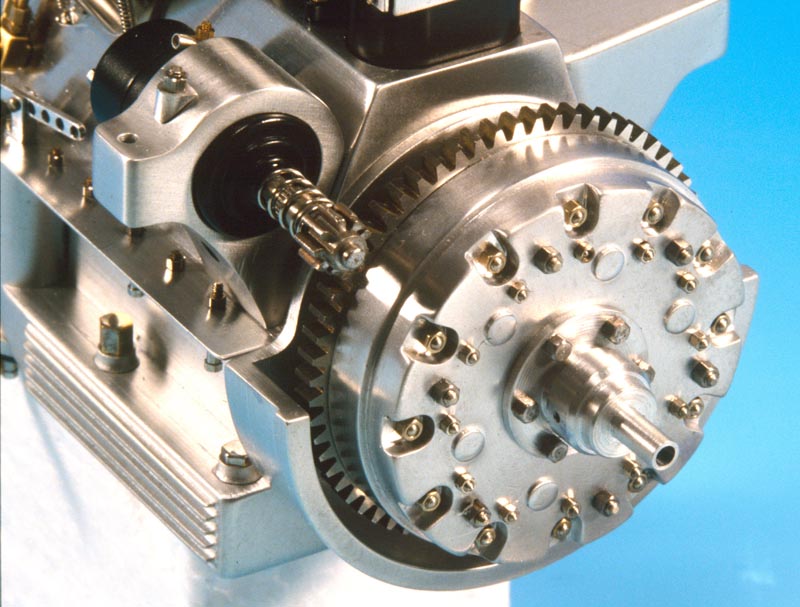
Another interesting part of the engine is the clutch. Due to the fact that it is circular in shape, I made it entirely using the milling machine. Finally, moving onto the largest pieces, I made the oil tubes and the starter motor—the starter motor being positioned on one of the engine support arms.
After these, the largest pieces, came the very smallest pieces such as cylinders, lids, oil distribution tubes, spark plugs, cables, and all the screws. In total, the engine is made up of almost 900 pieces.
The Bodywork
To make the bodywork, I fabricated a master copy from wood, which served to mould the brass sheet I used in the bodywork. I shaped the brass sheet using a hammer, and then assembled the additional parts with soft solder. The interior panels and the seats were made of wood, and then covered with leather. When the interior panels fitted well, I cut the doors out and made the hinges and locks.
Vanden Plas is the name of the company which produced the majority of the bodywork for Bentley during that period. The bodywork is distinguished by its elegant design, which makes it difficult to make the entire bodywork smooth. Additionally, it wasn’t an easy task finding leather the same colour as that used by Vanden Plas in the thirties.
The Mudguard
Although it appears to be a simple piece, it is in fact totally the opposite. It has a double curvature, and it’s an extremely complicated job to achieve this form perfectly. Using a rolling mill can make the job easier, although the head still has to be done using the lathe in order to reshape the brass sheet. The mudguards have one other laborious part, which consists of preparing and riveting the reinforcements for the support arms.
The Dashboard
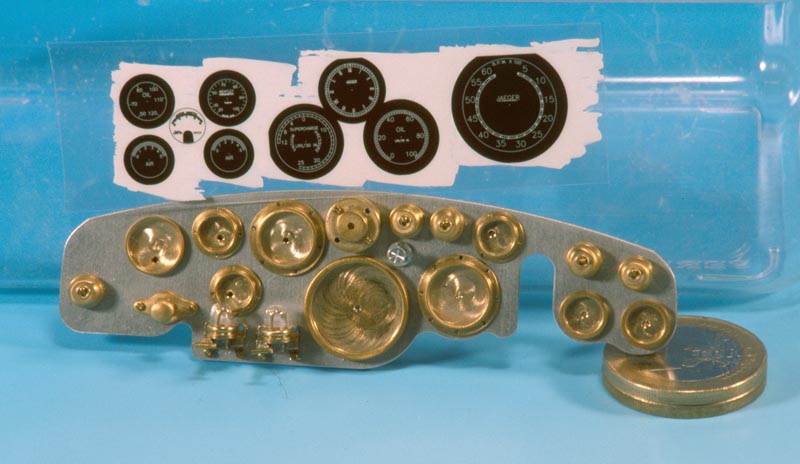
If we want to see a complex dashboard, then the Bentley is a perfect example. It has no fewer than nine clocks, five switches, and three other controls. To begin, I drew the plan of the layout of the clocks and controls.
Next, before separating it from the plug and using the wooden turning machine, I made the 969 circular marks. I kept the same order and sequence as on the original car, only ten times smaller. Next, I moved on to the lathe to make the bases of the clocks and the faces.
I then printed them at high resolution, which is essential for the size of them and the black background of the face. It also helped to prepare a cutting master with all the diameters of the faces, so I would be sure to cut them exactly to size. I also used it to cut the glass for the clocks.
To finish, the only thing left was to paint all the pieces, and then put it all together; the hands, the glass, and all the tubes and cables that go from this complicated dashboard to various parts of the car.
Finishing Touches
The steering wheel was made from brass, which I painted black. I then wound string around the hoop to give it the same effect as the original. The windscreen and the protective grill were also made of brass, and then nickel-plated. The system of bars on the roof will be the last parts to complete the model.
Several explanations failed to get a mention, but I’m sure you, the reader, will appreciate that any further detailed description would be a never-ending task!
—Francisco Pulido

