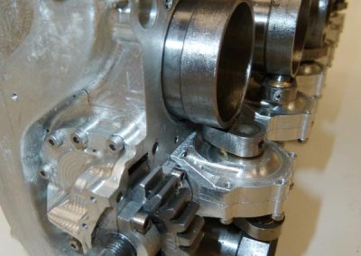
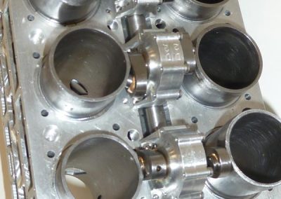
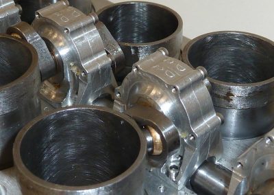
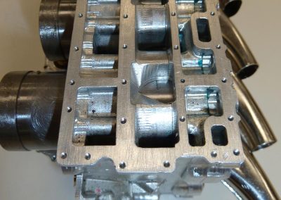
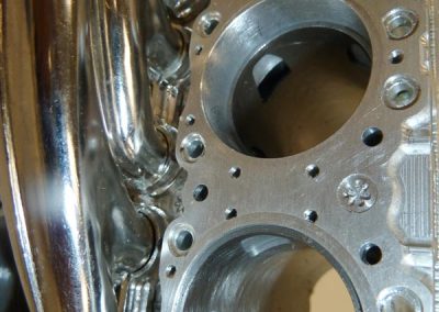
Below you can view more photos of Clen’s model Napier engines. Click on images to enlarge.
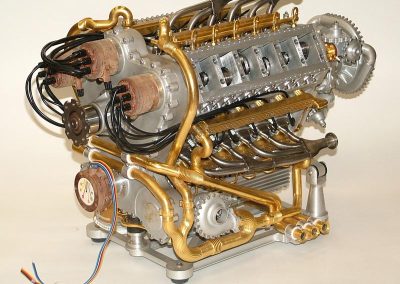
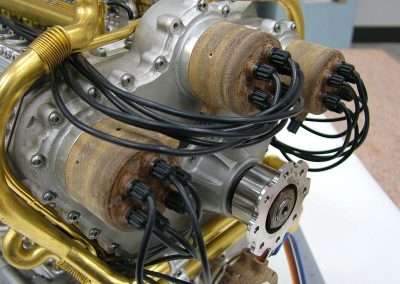
1/8 Scale Napier Deltic Engine
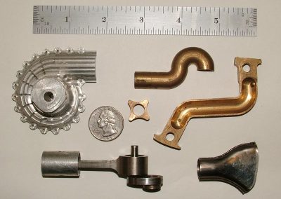
Deltic Engine Parts
Shown here are some extra parts for the model Deltic engine, some of which were CNC-machined. Many of the tubing parts were created as CAD drawings, which were then split down the middle and machined in two halves. Then the brass “tubes” were soldered together to complete the round cross-section while assuring that the complicated plumbing would fit perfectly. In the lower right is part of the delicately welded sheet metal exhaust system.
Deltic Demonstration Model
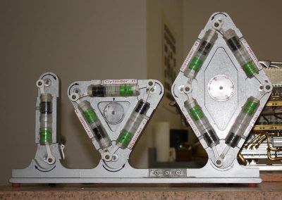
Clen also created this demonstration model to illustrate the complicated motion of the Deltic’s three crankshafts and three banks of cylinders. It features the original Junkers two opposed pistons in one cylinder on the left. In the center is the triangular configuration of the Deltic engine. On the right is a diamond shaped four-crankshaft design which Junkers also tried. The secret to getting the three-crank motor to move pistons in the correct directions was to reverse the direction of rotation for one of the three crankshafts.
Clen Displaying the Deltic Engine
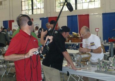
In 2011, Clen flew out from England and spent a few days at the Craftsmanship Museum before taking his Deltic engine up to the Western Engine Model Exhibition (WEME) in Pleasanton, CA. A video crew hired by the show promoters interviewed Clen about his marvelous model engine. Clen’s display was very popular with the crowd.
Napier Sabre Engine
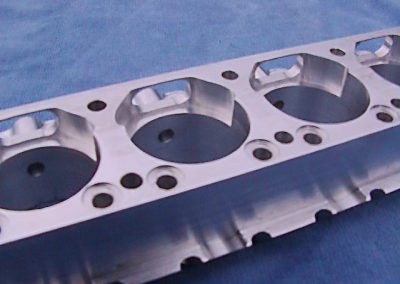
Sabre Cylinder Head
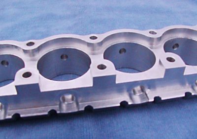
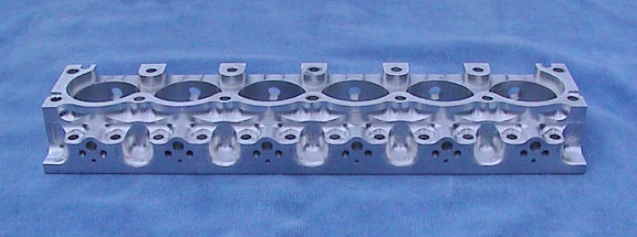
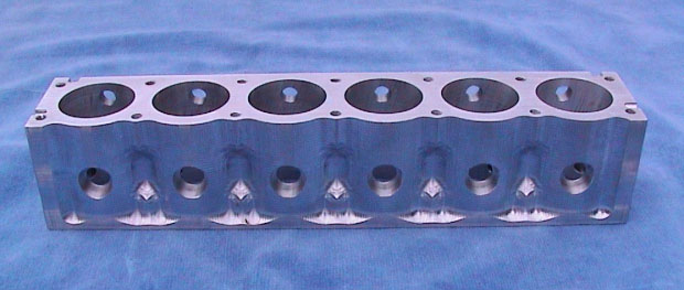
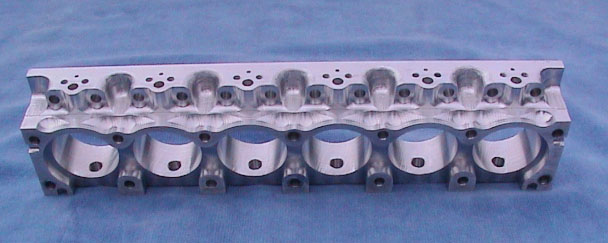
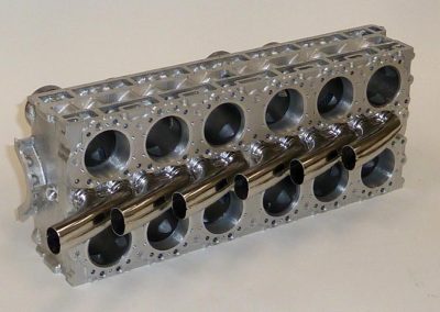
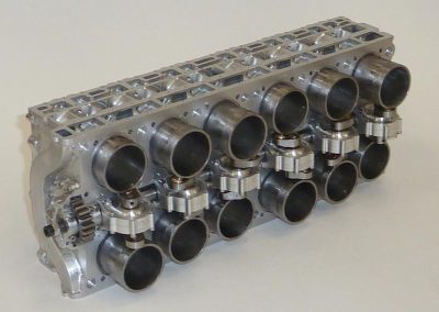
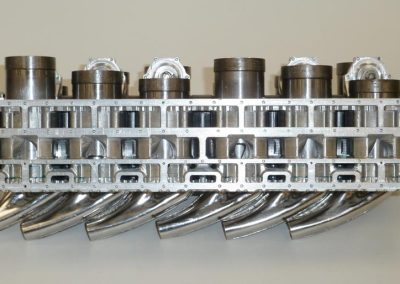
An overall view of the spare cylinder head that Clen made for his model Sabre engine.
Sabre Cylinder Head
The head was machined in layers to be able to duplicate the complicated intake, exhaust, and water passages from the original casting. Some of the tight-fitting joints between the layers can be seen here.

