Building Rarely Modeled Hot-Bulb Engines That Run
Introduction—What is a Hot-Bulb Engine?
Early on, most 4-cycle engines were not ignited by a spark plug; rather, they were ignited by an element heated via blowtorch. This consisted of a hollow ignition tube, or hot-bulb, that was connected by a throat or channel to the combustion chamber. In very early hot-bulb ignited engines, the fuel and air were sucked into the combustion chamber via one or two intake valves. Some engines had an intake valve for fuel (often gas), and one for air. The mixture was then ignited by compression into the hot-bulb. The ignition timing could be controlled by moving the blowtorch in or out along the hot-bulb.
A typical hot-bulb style ignition was often bigger, with a larger inside volume, and a different shape from the ignition tube. The fuel was usually injected by a low pressure injector directly into the hot-bulb at the inlet stroke. In most cases, the injector was water-cooled to prevent the fuel from boiling. The ignition timing depended on several factors: the amount of heat in the hot-bulb, the inside volume of the bulb, the compression ratio, the type of fuel, and the injection timing of the fuel.
Find’s very first hot-bulb engine was built in 1984. It was inspired by a Crossley gas engine, several of which can be found on the island where he lives.
On some engines, the compression ratio could be changed with a cast iron block to suit different kinds of fuel. This cast iron block had two different shaped sides, and was bolted to the compression chamber. By turning the block upside down, the compression chamber would shrink or enlarge, thereby changing the compression ratio. Water injection was sometimes added to cool down the hot-bulb on a hard working engine, thus preventing pre-ignition.
Starting around 1892, the English engine builder Richard Hornsby pioneered the making of hot-bulb engines with injected fuel. Then, around 1902, a Danish engine builder named Hein began making hot-bulb engines mainly for fishing boats. Later on, the four-stroke hot-bulb engines were replaced by a two-stroke, then semi-Diesel, and finally Diesel engines.
About Find Hansen
Find Hansen was born in 1948, and lives on a small island called Bornholm, which is a part of Denmark. He lives in a city called Gudjem, close to the Easter Sea. Find moved from Copenhagen to Bornholm in 1970, and bought an auto repair shop in 1972, in a town called Østerlars. He was still running that shop at the time of this writing, repairing vintage cars and old sport cars like Jaguars, MG’s, and Porsches.
Later, in 1999, Find bought a house in Gudjem where he and his wife now live. The new house has a splendid view of the sea, and plenty of room for an indoor workshop. Additionally, the house has a big room for Find’s wife to weave—giving the pair ample room for their respective hobbies. Find has two small lathes and an assortment of hand tools in his home shop. When it comes to bigger tasks—like turning flywheels, welding steel bars, using a metal bandsaw, or working on an angle grinder—Find goes to his auto shop. The auto shop also has an old, but accurate, 1-meter English lathe.
Now, it’s worth noting that Find has no formal education in car repair or engineering. He is completely self-taught. Find likes the excitement and challenge of making new engine parts. There are many things to consider when making these parts, and he must juggle many ideas in his head. Some of these factors include: choosing materials, choosing the right scale, picking the right machinery, deciding where to start and finish, and, of course, making the necessary drawings.
However, Find noted that one of the most exciting moments of any model build is the first test run, or “first pop,” of a new engine. The first pop is usually accompanied by several questions. Does the engine start easily? Is the injector and injection pump working properly? Is the compression good; with no leaking valves, piston rings, or gaskets? Naturally, there are always some adjustments to be made.
Find’s second engine was built in 1988. It was inspired by an engine built on his island in 1906, called a Bornholms Maskinfabrik. This is a four-poster, hot-bulb engine with fly-ball governor, which controls the injection pump (visible above) and a water-cooled injector.
There are certain demands when it comes to small, lamp-start, hot-bulb engines working with injected fuel. This is especially true if you want them to run slow and proper at about 350-400 rpm, and if a continuous blow-lamp is being used.
To start, the fuel must be right. Find has tried fuels from Diesel to turpentine, and the engine works with either. Diesel is smoky and sooty, but easily maintains the heat of the hot-bulb system. Conversely, turpentine burns much cleaner, but vaporizes faster than Diesel; thereby “stealing” more heat—which means a colder hot-bulb system.
Additionally, the compression must be good, because the heat it produces is necessary for ignition. Most of the combustion must take place in the hot-bulb, so a compression ratio of at least 7:1 is needed.
However, the hot-bulb system on one of Find’s models is slightly different than one on a full-size engine. It cannot simply be scaled down.
First, a reliable injector, injection pump, and a working governor system must be made. The model engine also needs to have good cylinder lubrication. The lubrication is needed because when dealing with vaporized fuel, like kerosene or turpentine, there is a tendency for the oil to wash off of the cylinder wall when the engine is cold. However, that and other problems will be addressed below.
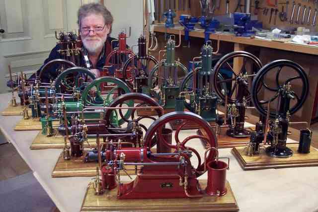
Mr. Hansen has made model engines for many years. He began around 1980 with steam engines, and then moved to four-stroke gas engines with high tension, or hot-tube ignition. Find’s latest models are four-stroke, lamp-start, hot-bulb engines. They have a bore of 20 mm, and a stroke of 30-36 mm. None of his engines are scale models; rather, they are so-called “freelance” engines of his own design. These designs were inspired by engines built in England around the turn of the century, such as Crossley, Hornsby, and Blackstone. Mr. Hansen submitted the following essay to expand on why he likes to work with old engine designs.
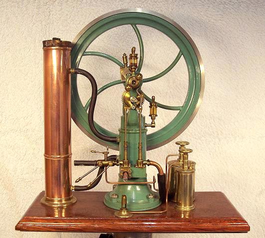
This inverted hot-bulb gas engine was built in 1989. The bore is 20 mm, with a 24 mm stroke, and it runs on lighter fuel.
Why I Like Old Stationary Engines
By Find Hansen
Some years ago, I started visiting a friend of mine named Poul. He was a collector and had collected, among many other things, stationary engines. He often started an engine when I came, and one day he started a horizontal 5 hp gas engine—an English engine called Crossley—built in 1896 with a big curved-spoke flywheel. The engine was “born” with hot-tube ignition (the tube was made of porcelain). However, it was later converted to high-tension ignition, with a Ford Model T carburetor, and used petrol instead of gas. I was very interested in the engine, and it was fascinating to see it run. It was a real slow runner, turning only about 120 rpm. Most engines were quite open at that time. They were often called “open crank” engines, and that is an engine type that I do like. You can see all the moving parts, and the pistons traveling in and out. Even if you are not an “engine man,” you will get an idea of what is happening and how things work.
I think that many model steam builders feel the same about steam engines. There are certain sounds when an old engine is running: the clicking cam followers; a hollow sound when the piston returns; a deep weak rumble from the main bearings; the intake and, of course, the exhaust; and if you are listening very carefully you can sometimes hear the ignition.
When engine builders in those days built engines, they were made to be good and reliable, and to have a long lifetime. But another very important thing was the appearance of the engine. I think that you can call it some kind of “engine art,” because some of the engines were really beautiful to look at, and many things were done to achieve that look. For example, the shape of the base and its profiles, the brass handles, the copper pipe work, the fly-ball governor, the oilers and sight feed lubricators, and last but not at least, the finish painting. A lot of grinding work had to be done to the rough cast iron before painting.
Well, back to Poul and his Crossley… We talked about making a model of the engine, and I thought it was a very good idea. I did some measuring of the flywheel crankshaft base, piston, etc. and drove home to start making the drawings. It would be scaled down at 10:1, as at this size you can display it on a shelf in the living room. I finished the engine, but it never became exactly the same engine as Poul’s, nor was it ever meant to be that, either. I just tried to make an internal combustion engine, and get it to run—and so it did.
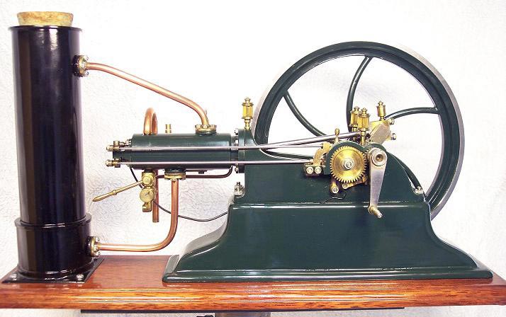
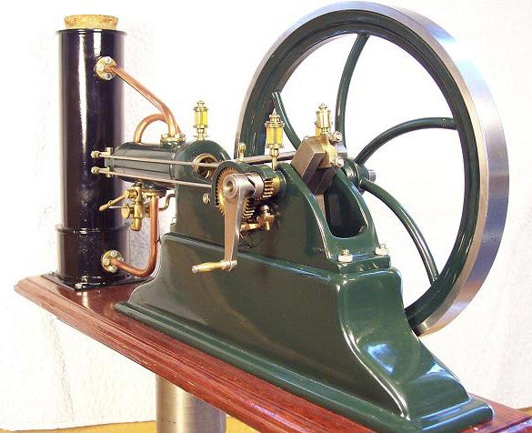
Find made this horizontal hot-bulb engine in 1990. The bore is 20 mm, with a 24 mm stroke, and it runs on kerosene.
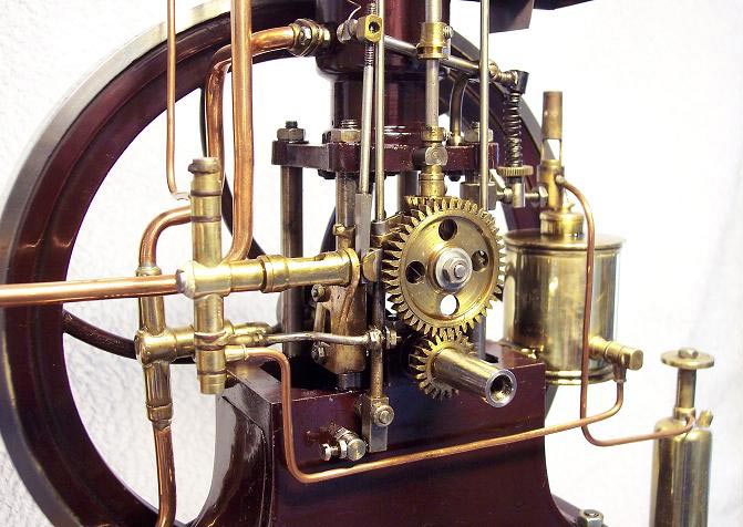
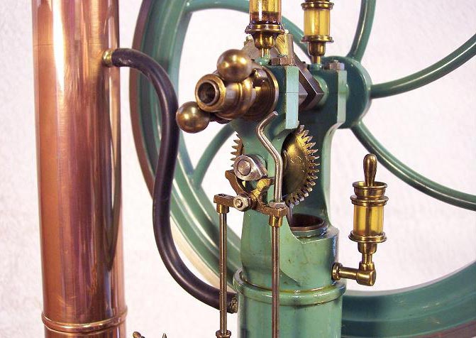
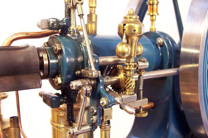
This photo shows a close-up of the fly-ball governor, side shaft with injection pump, cam, and valve cams. It also shows the cylinder head with an inlet valve on top, and an exhaust valve on the bottom. Having no milling machine, Find had to make the worm gears on a lathe. They connect the crankshaft to the side shaft, and the side shaft to the fly-ball governor.
Then Came My “Hot-Bulb Model Engine Life”
On another visit to Poul’s, he started a lamp-start, hot-bulb engine called Bornholms Maskinfabrik, which was built on my island in 1906. The engine had spent its working life at a farm before electricity. With this engine, the start procedure was a bit more exciting. The hot-bulb had to be heated before starting the engine using a blowtorch. The original blowtorch was missing, so Poul used a gas blowtorch. While the hot-bulb is heating you have time to check the engine: top up the oilers, lubricate moving parts, check for water, check fuel level, and bleed the fuel injection system if necessary.
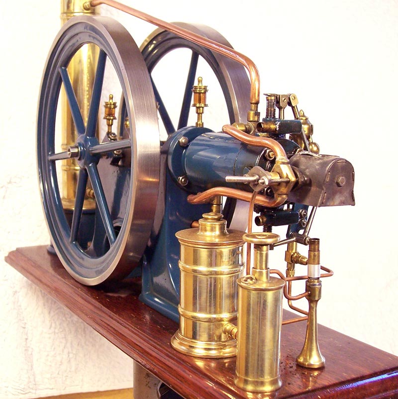
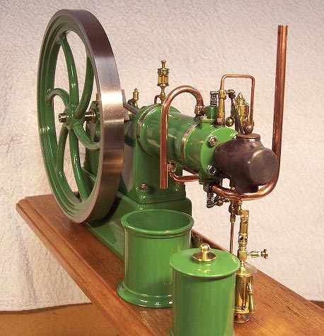
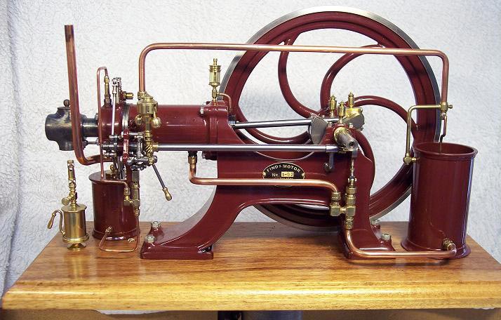
A typical hot-bulb engine. The unpainted component at the end of the cylinder housing is the hot-bulb cover. The hot-bulb and vaporizer tube are inside. The polished brass item below is the blow lamp, which functions like a small torch to heat the hot-bulb until it glows. This ignites the mixture inside the cylinder without using a spark.
Starting a Hot-Bulb Engine
Heat the hot-bulb until it becomes brown red with the blowtorch. This takes about 5-10 minutes. Then, two quick pulls at the injection pump handle, or if no start-handle is available, turn the flywheel by hand slowly forward until the compression just begins. Then turn the flywheel backward as fast as possible, and let go of it just before compression. If everything is OK, the engine will ignite and turn forward. (This requires a bit of practice.)
A funny thing about hot-bulb engines, whether 2 or 4-stroke, is that most can run both forward and backward. When it happens that the engine runs backward, most engineers know how to return to forward without stopping the engine, just using the injection pump handle at the right moment.
Poul and I talked about building a lamp-start hot-bulb engine, and Poul said, “This time you will have to deal with many difficult things. First, you will have to make a useful workable mini-injection pump and governor system (injection engines must have some kind of governor system or they will be completely out of control), an injector that must be water-cooled to prevent the fuel from boiling, and a hot-bulb of the right size. I won’t say that it is impossible, but it will be a very difficult job.” Then I said to him, “I will give it a try. The more the difficulties, the greater the challenges.” I went home and started to build my first hot-bulb model engine. I finished the engine, and after a long time, and with many experiments, I got it to run. Since then, I have improved many things on my engines, and today I think they run properly.
—Find Hansen
Built in 2002, this was one of Find’s first lamp-start, hot-bulb engines. In this case, the blowlamp can be extinguished when the hot-bulb is warm, and the engine is running. The bore is 20 mm, with a 30 mm stroke. The 4-stroke engine runs on kerosene.
Building the Parts
Find enjoys making the drawings, and he makes all of the parts for the engines by himself. None of the parts are made in a foundry; rather, they are constructed or fabricated from billet stock. The bases are made of flat steel bars which are cut with a bandsaw to get the right shape. Then, the bars are bent and welded together. The parts for the flywheel consist of three large steel rings with different diameters, six spokes (straight or curved), and a hub. Six holes for the spokes are drilled in the smallest steel ring, and in the hub. Then, the ring, spokes, and hub are silver soldered together. After that, the two larger steel rings are soldered together with the smallest steel ring. Then, the flywheel goes to the lathe for turning the sides and the outer rim. After painting the flywheel, it’s put back in the lathe to bore the hole in the hub for the crankshaft.
The crankshafts that Find makes are not built up in several parts. Instead, they are made from a solid round steel bar, or a flat square steel bar. Find turns them using his lathe and a four-jaw chuck with independent adjustable jaws. When a flat square steel bar is used, Find employs his metal bandsaw to cut off unnecessary material. The cylinder is made up of two pieces; a liner with space for the water, and a sleeve that goes around it to make the water jacket.
The piston is made from a solid round bar, which is 20 mm longer than the piston’s final size. First, Find bores out the inside of the piston, and then he turns the outside of the piston slightly larger than the finished size. Then, the piston goes to a four-jaw chuck on his Myford ML7 lathe, where it’s cross-bored to fit two large piston pin bronze bushings. The bushings are then silver soldered to the piston. Next, the piston goes back to the lathe to finish the outside surface, cut grooves for the piston rings, and cut a bit off the end to get the right length. The cylinder head is made from a solid piece of steel bar stock, which is drilled, bored and turned. Machining the cylinder head requires many tasks, including: making the valve chambers, valve guides and seats, the combustion chamber, the holes for the cylinder bolts, threads for the hot bulb, the hot bulb cover bracket, the rocker arm bracket bolt, and a short sealing bolt.
Find does not have a milling machine to make the worm gear wheels, so he uses a lathe. The teeth are cut out bit-by-bit, tooth-by-tooth. He uses a tool bit that’s ground to fit between the teeth of the worm gear. The headstock is connected to the leadscrew with gear wheels in the right ratio, and then the leadscrew is turned by hand.
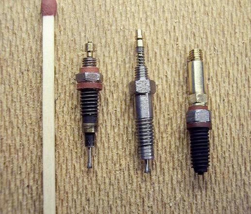
Three injectors sit by a wooden match for size comparison. The two on the left are only partially assembled.
Solving Problems Inherent in Scaled-Down Engines
There are certain difficulties encountered when making a small four-stroke, lamp-start, hot-bulb engine with injected fuel. First comes the hot-bulb system. It’s difficult to scale a hot-bulb system from full-size to a smaller engine if you want the engine to run without a continuous flame from a blowtorch. The heat from the hot-bulb will soon escape to the cylinder head and water-cooled injector, because of the short distance between these two elements. Therefore, Find had to make his own hot-bulb system. After making several different hot-bulbs, and spending many hours experimenting, he ended up with a useful one.
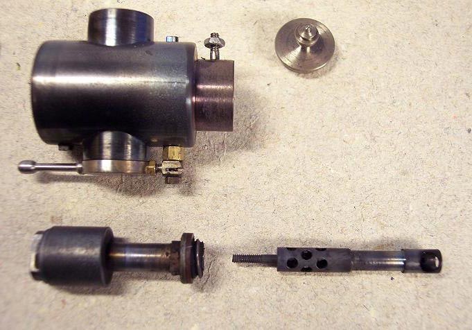
To prevent the heat from the hot-bulb from escaping to the cylinder head, the hot-bulb has a long, thin-walled neck with a wall thickness of 0.20 mm. To prevent the heat from escaping from the bulb to the injector, he has moved the injector from the bulb to the cylinder head. By doing so, he created an indirect injection—not into the hot-bulb, but on a vaporizer tube connected to the inside end of the hot-bulb.
When the hot-bulb is heated, the vaporizer tube is heated, too. On the hot-bulb end, the vaporizer tube is cross-drilled with several holes. On the injector end, the vaporizer tube is cross-drilled with only one hole, where the fuel is injected.
Next, Find had to make a governor system, an injection pump, and a useful injector. The governor system could be a hit-and-miss setup, but Find prefers a fly-ball controlled injection plunger pump. Therefore, he made a system where a fly-ball governor is connected with a conical bar. This bar is situated between an injection pump cam, and an injection pump plunger. So, when the conical bar is moved in and out by the fly-ball governor, the stroke of the plunger will be changed as well—thereby giving more or less fuel to the injector. Find soon learned that there must be no leak at all between the ejector valve and the valve seat. It would stop the engine if just a tiny bit of air from the compression, or gas from the combustion, got into the injector.
The valve head was turned on a lathe to have an angle of 14°, and then polished with very fine sandpaper. The valve has a threaded stem so that the valve spring can be adjusted to the right fuel pressure—locked with one nut, and unlocked with another nut. The valve stem is 0.90 mm thick. The injection pump is an ordinary type, with one inlet and one outlet ball valve, and a plunger. The balls are 1 mm, and the plunger is 18 mm long and 2 mm thick. He found that when the engine runs at an idle speed of about 360 rpm, with no load, the plunger only moves 0.03 mm.
The blowlamp, or blowtorch, works with lighter fuel. The gas flame is controlled by a small needle valve. The problem with a smaller blowlamp is that it must deliver enough heat to warm the hot bulb in the short, thin flame tube. If you turn the gas needle valve up too much, the flame will blow out. His solution was to cross-bore the flame tube so that a small bar could be placed there. This split the gas flow to slow it down, which worked!
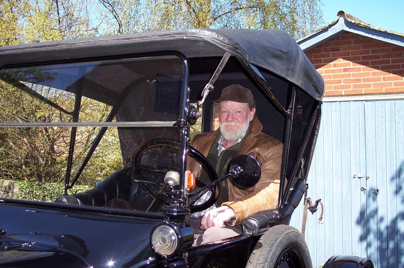
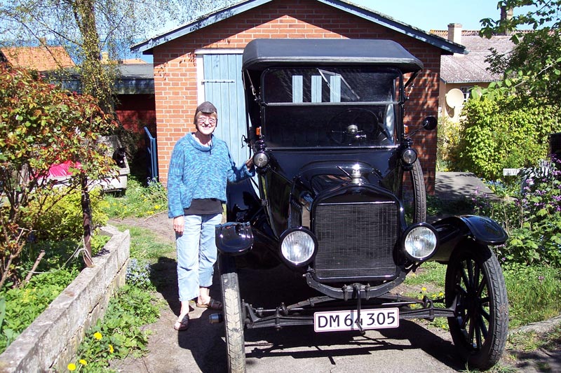
Find and his wife enjoy restoring, and driving, their vintage Ford Model T.
Building a 12 cc Diesel Model Engine
In 1995, Find Hansen tried to build a true Diesel model engine with injected fuel, but had no success. He ended up turning it into a hot-bulb engine instead. In the time between, Find dreamt of taking on the Diesel project again, and now finally has one running. The engine has a bore of 20 mm, a 40 mm stroke, and a compression ratio of 21:1. The engine does not use a pre-chamber, but has a direct injection. It was running on kerosene at the time of this writing.
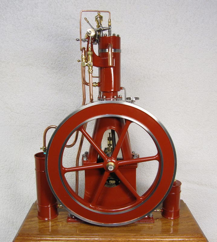
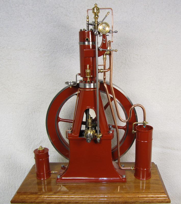
The Diesel engine is vertical, and has an A-frame construction, like the old Danish-built B&W blast injection Diesel engines. He built the engine and the crankshaft stronger this time around, with thicker journals to withstand high compression. Then, Find drilled an oil passage in the crankshaft to have a continuously lubricated big end.
Starting the Engine
Find noted that, “At the first start attempt, I tried to start the engine using ether Diesel start. It started and ran, but only on the Diesel start, not on the engine fuel. At the third attempt, the flywheel broke loose. I fixed the flywheel, and tried again using Diesel start. This time it started and ran on the fuel. I tell you I was happy!” On the following attempt using Diesel start, the engine picked up, but made an awful noise. The connecting rod was bent, but luckily nothing else had happened to the engine. Find made a new connecting rod, now 6 mm thick. (The old one was 5 mm.) However, during Find’s next start attempt he thought, “No more Diesel start, why not try to use my wife’s hair dryer?”
So, Find took the hair dryer, and when it was warm to the touch he tried to start the engine. He found that he couldn’t hand-crank it because of the high compression, so he used an electric drill. To his surprise, the engine started and ran! Since then, Find has experimented with injection pressure, the injection timing, and different kinds of fuel. He found that it’s very important for the injection timing to be just right. Even just a few degrees before or after, and the engine will not run properly.
Find Hansen first started working on this Diesel engine in 1995. In 2011, 16 years later, he finally crafted one that runs to his satisfaction.
Find made a video explaining the operation of each valve on the Diesel engine.
Thoughts on Building a Small Scale Working Diesel Engine
By Find Hansen
- The compression must be about 100% with no leaky piston rings, gaskets, or valves, because the compression heat is the only igniter.
- The compression ratio must be at least 20:1 for an easy start, and 22:1 would be better. You should not be afraid of the high compression. The engine starts, runs, and works much better.
- The injector must atomize the fuel very well, because the compression heat is the only thing to vaporize the fuel before it is ignited.
- Using a light fuel like kerosene, instead of Diesel, is better, because it vaporizes and ignites more easily. It’s not as smoky as Diesel, either.
- The crankshaft, crankshaft bearings, big end bearing, piston pin, and connecting rod must be made bigger and stronger to withstand the high compression. This is because the load on a 20 mm piston, with a compression ratio of say 21:1, is about 160 kg, and when the fuel is ignited the load is about 180 kg. When pre-ignition occurs (Diesel knocking), the load rises to about 220 kg. It is a wonder that the engine will stand this heavy load. Also, the whole engine construction must be made stronger.
- The main bearings, and especially the big end bearing, must have good, continuous lubrication while the engine is running.
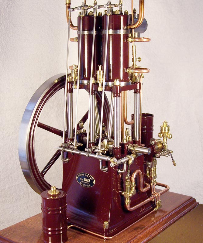
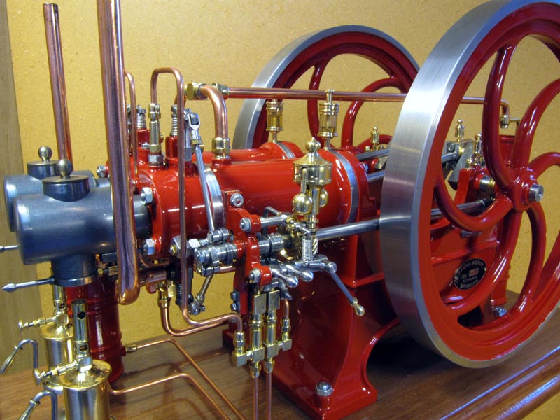
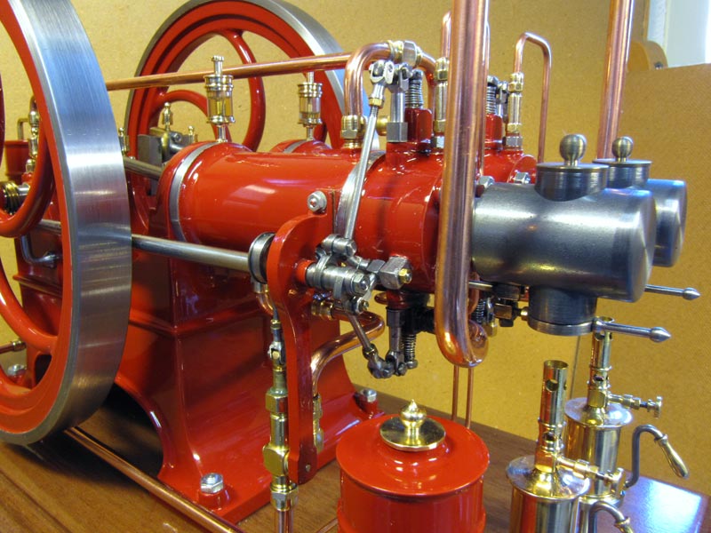
This twin-cylinder horizontal hot-bulb engine is one of Find’s more recent creations. He submitted these photos in September, 2010.
Find’s Hot-Bulb Engines in Action
In addition to the photos here, there are also a number of videos of Find’s hot-bulb engines in action on his personal YouTube channel.
View more photos of Find Hansen’s unique hot-bulb engines.

