The Opposite of Miniature Model Engineering
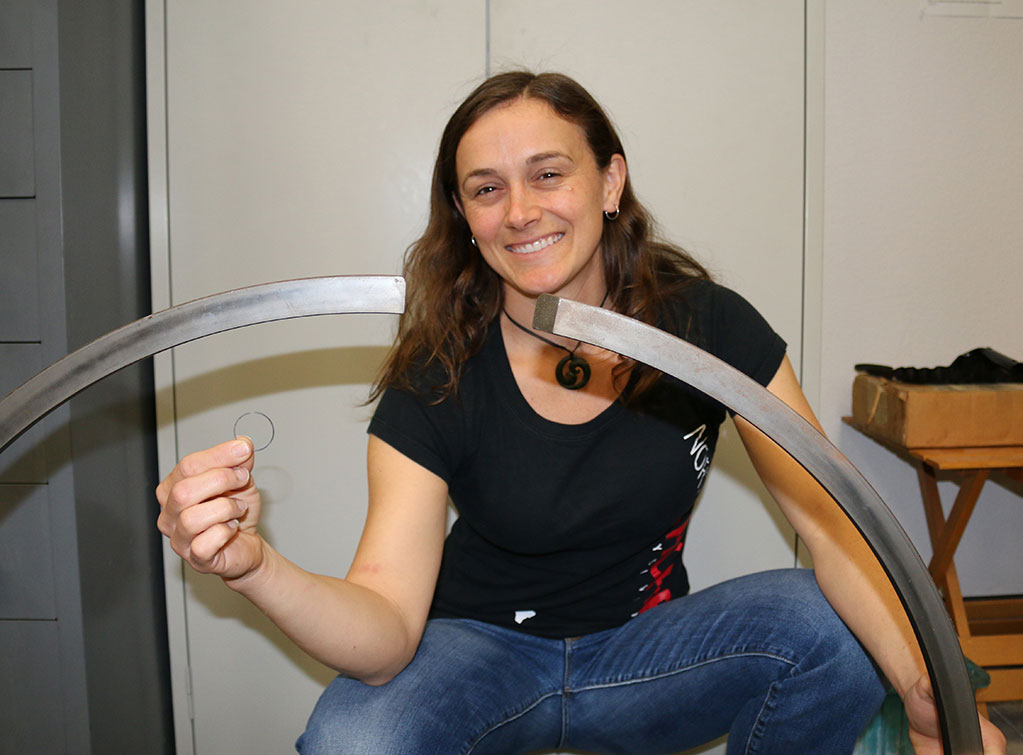
Kelsey Barrion visited the Miniature Engineering Craftsmanship Museum in late 2015. She brought along a piston ring from a giant Diesel engine that she was working on. In her other hand is the tiny piston ring from the Kinner 5-cylinder radial engine that was being built in the museum’s machine shop. Below, she explains what goes into keeping some of the world’s largest Diesel engines running.
Giant Container Ship Diesel Engines Offer Unique Challenges
My name is Kelsey Barrion, and I’m a Marine Engineer. I work on large cargo ships operated by various companies as a member of the Marine Engineers’ Beneficial Association (MEBA). I got started in this field over a decade ago when I attended the US Merchant Marine Academy (USMMA), where I completed a four-year degree in Marine Engineering and Shipyard Management that included one year at sea as a cadet on US-flagged merchant vessels.
I stumbled on the Miniature Engineering Craftsmanship Museum in mid-2015, and was so impressed with the talent and skill that went into the projects on display that I dragged my family back with me when they came to visit for the Christmas holiday – and just for fun, I brought along a used spare part from the ship I’d just worked on for comparison. That piston ring generated a discussion about large engines (in excess of 4,000 horsepower) and how they work. Since most people never get to see one in action, Craig asked me to write a bit about it.
The ship that the ring came from is the M/V RJ Pfeiffer, operated by Matson Navigation, LLC. She’s 713 feet long and carries 2,229 TEU (containers). She weighs in at 27,100 LT and does 23 kts at sea speed, but those are deck particulars. The important stuff is this: she operates on a single screw (propeller), which is directly coupled to an 8-cylinder, turbocharged, two-stroke, 33,680 HP, slow speed diesel engine built by MAN in cooperation with Daihatsu.
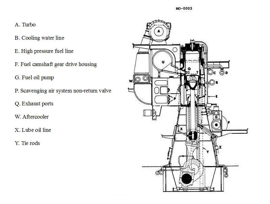
Let me start with some photos of the engine [Editors note: Sadly, Kelsey’s photo link is no longer functional. Instead, see the photos on this page]. Unfortunately, since the engine is about five stories tall, I can’t show you the entire thing in one image. But a cross-sectional drawing would look something like the one below.
The engine is termed “slow-speed” or “low speed” because full speed – generating 33,000 BHP – is 88 RPM. This engine is actually on the smaller side of large slow-speeds, as the most powerful versions have as many as 14 cylinders and can put out over 100,000 HP. But with each piston being 80 cm in diameter and traveling nearly a meter with each stroke, it’s still impressive in operation. One single piston – without the piston rod attached – weighs nearly as much as a car, and when the engine is in operation, you can actually see the individual cylinder head assemblies moving when each cylinder fires.
In order to keep the engine from shaking itself apart, each piston and piston rod travel only in the vertical direction. The bottom end of the piston rod is connected to a crosshead bearing, which absorbs the side thrust from the rotation of the crankshaft. The crosshead bearing is connected to the connecting rod, which is in turn connected to the crankshaft journal, which has the appropriate counterweighted webbing on each cylinder. We have a separate lube oil system for the crankshaft and sump than we do for the camshaft or even the cylinder itself, in order to protect the camshaft from the byproducts of combustion, which inevitably contaminate the main lube oil. The camshaft and crankshaft/main sump use the same type of oil, but the cylinders use a completely different, lighter oil that is consumed in the combustion process.
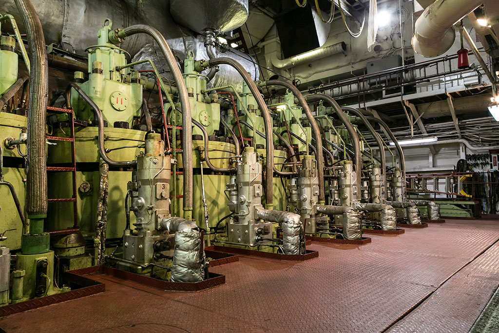
Here you can see the cylinder head level, with the exhaust valves and exhaust manifold.
The crankshaft has a large chain drive at one end which sets the timing for the camshaft. The camshaft controls both the operation of the exhaust valves and the operation of our fuel pumps, which take the fuel and boost it to approximately 350 bar for injection. Because the engine is directly coupled to the propeller shaft, the cams are built with pneumatic shifters that alter their position on the camshaft. When we need to go astern, we bring the engine to a stop, shift the cams and start it again in the opposite direction.
Because the engine is a two-stroke, each cylinder is constructed with air ports at the bottom which are uncovered when the piston travels toward bottom dead center (BDC). The ambient air for combustion is compressed by the turbochargers (there are two) and fed to a scavenge air receiver, which is connected to all of the cylinders’ scavenge air ports. When the piston uncovers the ports, dense pressurized air is forced in until the piston rises above them and travels back toward top dead center (TDC). The air is compressed, fuel is injected through the two injectors (weighing about 35 lbs each) mounted in the top of the cylinder head, combustion occurs, and the piston travels down on the power stroke. When the power stroke is completed, the exhaust valve located at the top of the cylinder is opened by forced lube oil and combustion gases exit the top of the cylinder to the exhaust manifold, where it is used to power the turbochargers before exiting out the stack. Each exhaust valve stands about three feet tall and weighs approximately 150 lbs. The valve body assembly which houses it is closer to 2 tons.
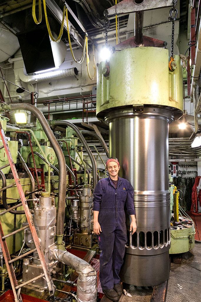
Kelsey next to one of the new cylinder liners, which replaced one that had worn down too far.
Although we call it a diesel, the fuel we usually burn is something most people would think of as asphalt, just without the sediment. It’s called Heavy Fuel Oil (IFO 380). We prefer HFO over Marine Diesel Oil (which we also burn) because of the greater Higher Heating Value (HHV) and therefore power developed per ton. However, the fuel is thick and prone to high sediment and sulphur content, so we have to work hard to heat it, purify it, and then make sure we keep our stack (exhaust) temperatures high enough that the sulphur in the exhaust gas doesn’t condense and corrode the stack. In a 35-day round trip (the route is currently Long Beach – Honolulu – Guam – Xiamen – Ningbo – Shanghai – Long Beach), we burn approximately 3,000 metric tons of HFO.
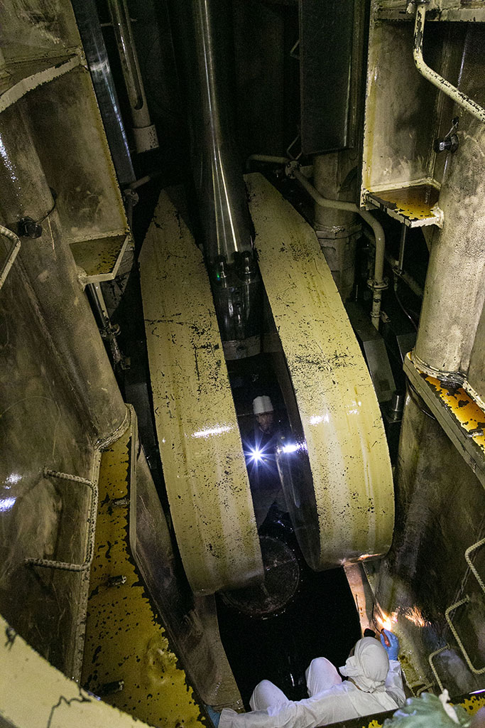
Pictured here is the Chief Engineer and First Assistant Engineer in the crankcase. They’re performing an inspection of the main bearings, which as in any engine are absolutely critical.
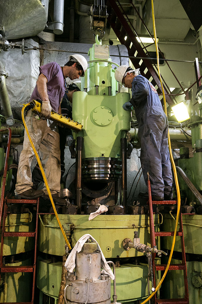
The attached photos are the ones I thought would best help give an idea of what it’s like to work on this engine. One is just the cylinder head level, with the exhaust valves and exhaust manifold. Another is me next to one of our new cylinder liners, which was replacing one that had worn down too far. A third is our Chief Engineer and First Assistant Engineer in the crankcase, performing an inspection of the main bearings, which as in any engine are absolutely critical. The last photo is a couple of our engineers placing an exhaust valve assembly (complete with body) back on the engine after maintenance. Every 35 days, one piston of the engine is removed, inspected and fitted with new rings and whatever other components are required for the cylinder based on the findings of the inspection. It makes for a hectic port stay, as you only have a couple days and the ship can’t move until the engine is back together. Many of the major fasteners (nuts/tie bolts) are large (around 105mm), and so it’s either slugging wrenches and sledgehammers, or special hydraulic jacking nuts that help us achieve the torque we need without causing material failure.
As for the engineers, we sign on for three to four months at a time and ride the ship wherever it goes. When our time is up, another MEBA engineer replaces us and the ship moves on. Even though a majority of the goods carried in and out of the US move by ship, very few of them are American hulls, and the industry as a whole rarely enters the average person’s consciousness. If anyone is interested in the industry as a whole, I highly recommend Ninety Percent of Everything by Rose George.
For those interested in learning more about large diesel ship engines from the past, present and future, follow this link.
—Kelsey Barrion

